Yeti Cycles SB6C Bedienungsanleitung
OWNER’SMANUAL
2014YETI SB6C

4. 5.
TABLE OF CONTENTS
BRAND OVERVIEW 06
FRAME FEATURES 08
GEOMETRY 10
MAINTENANCE SCHEDULE 12
SETUP
OVERVIEW 12
SHOCK SETUP 14
DERAILLEUR HANGER INSTALL 16
CABLE/LINE SETUP 18
TECHNICAL
ASSEMBLY OVERVIEW 20
EXPLODED VIEWS 26
REBUILD KITS 38
LEGAL
WARRANTY 30
CONTACT INFORMATION 31

6. 7.6. 7.
WELCOME TO THE TRIBE.
CONGRATULATIONS ON YOUR
PURCHASE OF A NEW YETI.
We are condent your new bicycle will exceed
your expectations for value, performance, and
ride quality. Each frameset and component
has been custom specied and designed to
enhance your riding experience. Whether you
are a beginner cyclist, or a seasoned pro,
your Yeti bicycle will provide endless hours of
two-wheeled fun.
This model specic manual is designed to
be used in conjunction with the general Yeti
Owner’s Manual and the manuals supplied by
the suspension manufactures. If you did not
receive the Yeti owner’s manual or the manual
provided by the suspension manufacturer
download the materials off the Internet, or
contact your local dealer.
Bicycling can be a hazardous activity
even under the best of circumstances.
Proper maintenance of your bicycle is your
responsibility and when done properly helps
reduce the risk of injury and damage to your
bicycle.
This manual outlines basic setup and
maintenance recommendations of your new
Yeti. Because it is impossible to anticipate
every situation or condition that may occur
during the assembly, setup, and maintenance
of your bicycle, Yeti recommends that all
service and repairs be performed by your
local authorized Yeti Dealer.
This manual contains many “Warnings” and
“Cautions” concerning the consequences
of failure to maintain or inspect your bicycle.
The word “Warning” indicates a potentially
hazardous situation in which , if not avoided,
could result in serious injury or death. The
word “Caution” indicates a potentially
hazardous situation in which, if not avoided
may result in minor injuries or damage to
your bicycle or a component of your bicycle.
Be sure to read and understand all of the
Warnings and Cautions listed in the manual.
Warning: Make sure you review and understand the warnings, instructions, and content of this manual and accompanying
manuals for your bicycle.
Warning: Technological advances have made bicycles and bicycle components more complex and the pace of innovation is
increasing. It is impossible for this manual or the accompanying manuals to provide all the information required to properly
repair and/or maintain your bicycle. In order to help minimize the chances of an injury, it is critical for you to have work
performed by an authorized Yeti retailer.

8. 9.
THE LOWDOWN ON THE
SB6CAND ITS FEATURES.
1. The SB6c delivers 6 inches (157mm) of travel with our patented
Switch Innity Technology. Efcient pedaling performance while still
smooth and continuous when the going gets rough.
2. High modulus carbon provides a stiff, strong and light weight
chassis.
3. Oversized pivot pins help create a stiff interface between the
front and rear triangles of the frame. Custom Enduro Max sealed
bearings keep things moving freely at the pivots.
4. The ISCG 05’ tab is built into your SB6c. The built in system is
lighter than a conventional tab and allows for a full myriad of chain-
guide options.
5. Using our inset head tube on the SB6c allows for a larger head tube
with more area, increased stiffness, and lower overall ride height
without compromising any performance.
6. The SB6c uses a 2.5 inch stroke, 8.5 inch eye to eye Float-X shock,
by Fox Racing Shox.
7. Custom chain-slap guards on the seat stay and chain stay keep
things quiet while riding and protect the frame.
8. The SB6c features internal cable routing for clean protected cables
and a very clean looking bike.
9. The SB6c has a removable front derailleur mound specically
designed around the new Shimano side swing D-Type front
derailleur.
10. Dedicated Boost 12 x 148 dropouts for strength, stiffness and ease
of wheel installation.
1. SWITCH INFINITY TECHNOLOGY PATENTED SUSPENSION SYSTEM
2. HIGH MODULUS CARBON FIBER MAIN FRAME AND SWING ARM
3. OVERSIZED PIVOT PINS WITH ENDURO MAX BEARINGS
4. INTEGRATED ISCG 05 MOUNTS
5. TAPERED INSET HEAD TUBE (44MM/56MM)
6. SUSPENSION BY FOX (8.5 X 2.5)
7. CUSTOM CHAIN-SLAP GUARDS
8. INTERNALLY ROUTED CABLES
9. DIRECT MOUNT FOR SHIMANO SIDE SWING FRONT DERAILLEUR
10. DEDICATED BOOST 12 X 148 DROPOUTS
10. 11.
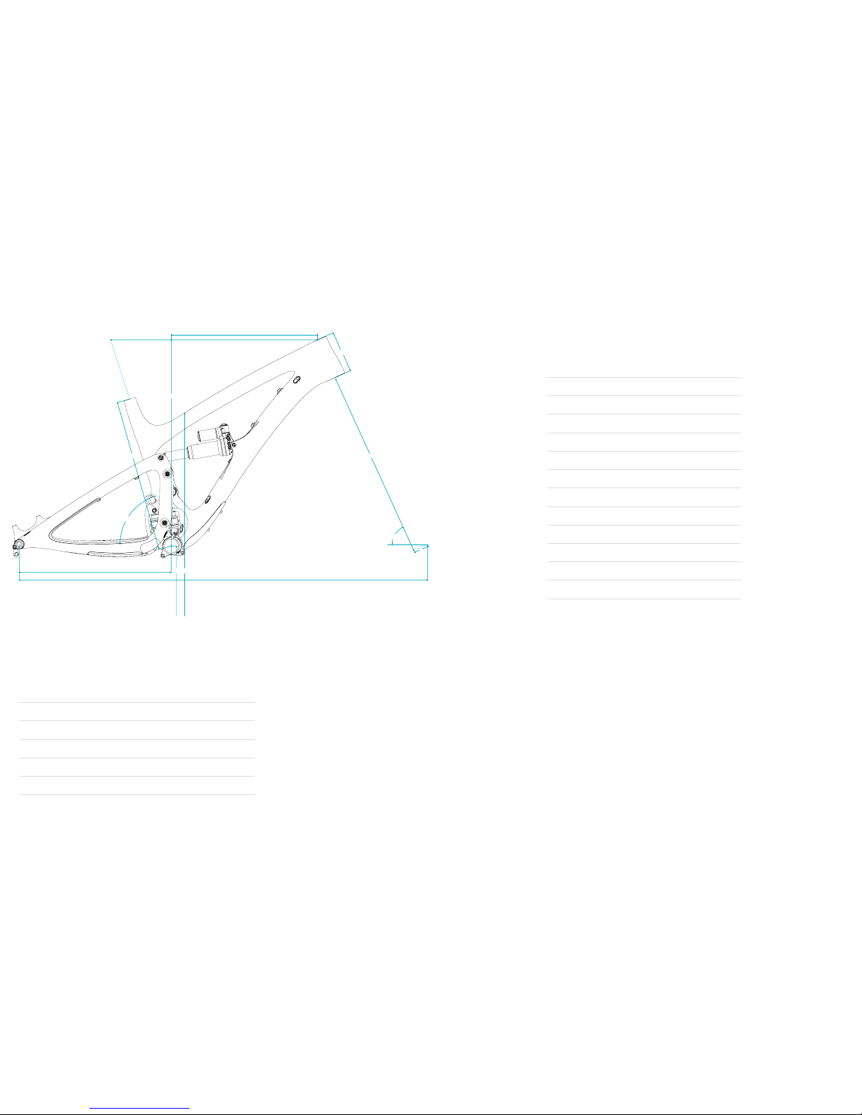
GEOMETRY
FIT
X-SMALL 4’11” (145CM) - 5’3” (160CM)
SMALL 5'3" (160 CM) - 5'7" (170 CM)
MEDIUM 5'7" (170 CM) - 5'11" (180 CM)
LARGE 5'11" (180 CM) - 6'3" (191 CM)
X-LARGE 6'3" (191 CM) - 6'6" (198 CM)
FOX 36 / 160MM FORK
XS SM MD LG XL
A15.0 16.5 17.5 19 20.5
B21.8 22.8 23.8 24.8 25.8
C65.5 65.5 65.5 65.5 65.5
D73.5 73.5 73.5 73.5 73.5
E17.4 17.4 17.4 17.4 17.4
F44.6 45.7 46.8 47.8 48.9
G13.6 13.6 13.6 13.6 13.6
H28.7 28.8 28.9 28.9 28.9
I3.7 4.3 4.8 5.6 6.3
J21.6 21.6 21.6 21.6 21.6
K1.73 1.73 1.73 1.73 1.73
L22.6 23.2 23.6 24.4 25.0
M15.1 15.9 16.8 17.6 18.3
All measurements are in inches
B
J
I
D
E
F
G H
M
L
K
C
A

12. 13.
KEEP YOUR YETI FRESH
AND CLEAN
OVERVIEW TORQUE
KEY TORQUE SPECS
Following these guidelines will help maintain the performance of your bicycle and prevent
more serious problems from arising. It is important to remember that service intervals can vary
depending on climate, trail conditions and riding frequency. If you are unsure about working on
your own bicycle, contact your authorized Yeti Dealer or visit the repair help section at www.
parktool.com for more information on general bicycle maintenance.
Yeti strongly recommends using a torque wrench when assembling your frame. Torque
specications for individual parts on the SB6c are listed below, as well as in the step by step
assembly instructions later in the manual. For general bicycle maintenance please consult the
torque specications of the manufacture’s component you are adjusting.
PART NUMBER DESCRIPTION TORQUE (NM)
300030151 BOLT TI MALE M6X1X12MM 7
300030057 INFINITY LINK BOLTS 12
300040454 COLLET BOLT M8 8
300040480 UPPER LINK COLLET AXLE 3
300040478 LOWER LINK AXLE 13
300040479 MAIN PIVOT COLLET AXLE 3.5
WEEKLY
MONTHLY
3 MONTHS
ANNUALLY
CLEAN AND LUBE CHAIN
CHECK TIRE PRESSURE
CLEAN BIKE OF MUD AND DEBRIS
CHECK BRAKE FUNCTION
CHECK SHOCK PRESSURE, IF APPLICABLE
CHECK FOR LOOSE BOLTS AND TIGHTEN, IF NECESSARY
CHECK HEADSET AND TIGHTEN / LOOSEN, IF NECESSARY
THOROUGHLY CLEAN PIVOT POINTS WITH A RAG (DO NOT LUBRICATE)
LUBE INFINITY LINK EVERY 40 HRS. (YETI HEAVY MOLYBDENUM GREASE)
REPLACE BRAKE PADS, IF NECESSARY
CHECK TIRES FOR WEAR
CHECK SPOKE TENSION AND RETENTION, IF NECESSARY
CHECK CHAIN FOR WEAR AND REPLACE IF NECESSARY
COMPLETE TUNE-UP PERFORMED BY AN AUTHORIZED YETI DEALER
SCHEDULE
14. 15.
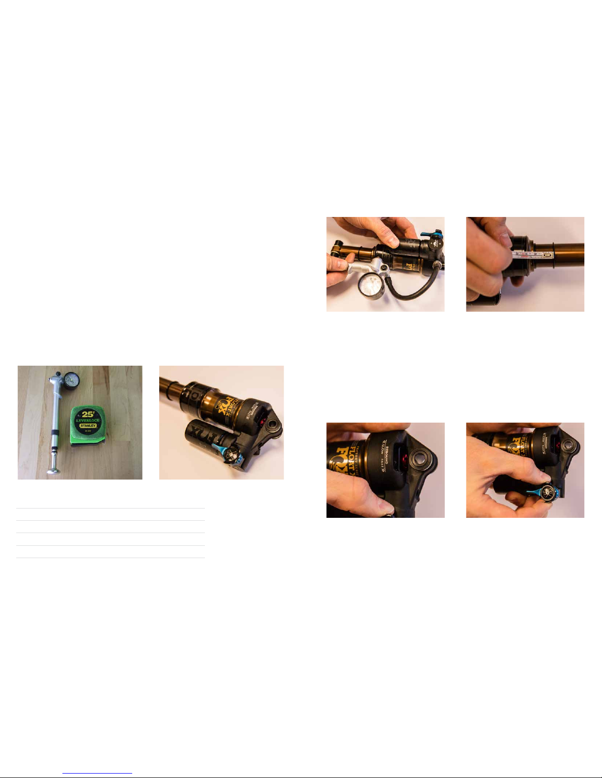
SHOCK SETUP
Inspect your shock for any visible damage.
If oil is leaking or you notice any damage to
the surfaces or seals, please contact the Fox
Racing Shox service center for repair at 800.
FOX.SHOX or your local bike shop.
Shock set-up can uctuate greatly based on
the rider. The set-up guide is intended as a
base line to get the rider started. Experiment
with your settings to nd the set-up that
works best for you.
YETI TIPS TOOLS NEEDED
• Shock Pump
• Metric Tape Measure
01. AIR PRESSURE 02. SAG
03. REBOUND AND COMPRESSION
The main air spring controls the sag of the shock.
For the SB6c to ride properly it is important to
setup the shock with the correct amount of sag.
The SB6c works best with 18-19MM of measured
sag. To increase the sag reduce the main spring
air pressure. To reduce the sag increase the main
spring air pressure. Cycle the shock 5-10 times
to equalize the EVOL chamber before measuring
sag.
Once you have set your baseline air pressure you
need to measure the sag. To measure the sag
slide the travel indicator (O-Ring) up against the
shock body. With a friend supporting the bike
and with the shock in “open,” sit on the saddle
(do not bounce) and allow your body weight to
compress the shock. Once you have compressed
the shock, get off the bike and measure the
distance between the shock body and the new
position of the travel indicator (O-Ring). This is
your sag.
The rebound has 14 clicks of adjustment. The rebound knob is the red adjustment dial located at the front
of the air can. When the shock is mounted on the bike a small allen wrench is the best way to rotate it.
Slower rebound- turn the knob clockwise, Faster rebound- turn the knob counter-clockwise.
Compression is adjusted 2 ways. Low speed compression can be tuned for the “open” position with the
black adjuster, giving the shock 3 positions. The Blue lever is a 3 position lever: Open, Medium and Firm.
For our bikes, unless you are on pavement, we recommend using the “open” setting. The Switch Innity
design will do the rest!
*All clicks are counted clockwise, rotating from the all the
way out or counter - clockwise dial position. Number of
clicks of rebound will vary based on air pressure.
ADJUSTMENT SETTING
AIR SPRING SETTING (PSI) RIDER WEIGHT LESS 10 PSI
MEASURED SAG (MM) 17-18MM
REBOUND *5 CLICKS
TRAIL ADJUST OPEN (DESCEND)
QUICK START GUIDE
16. 17.
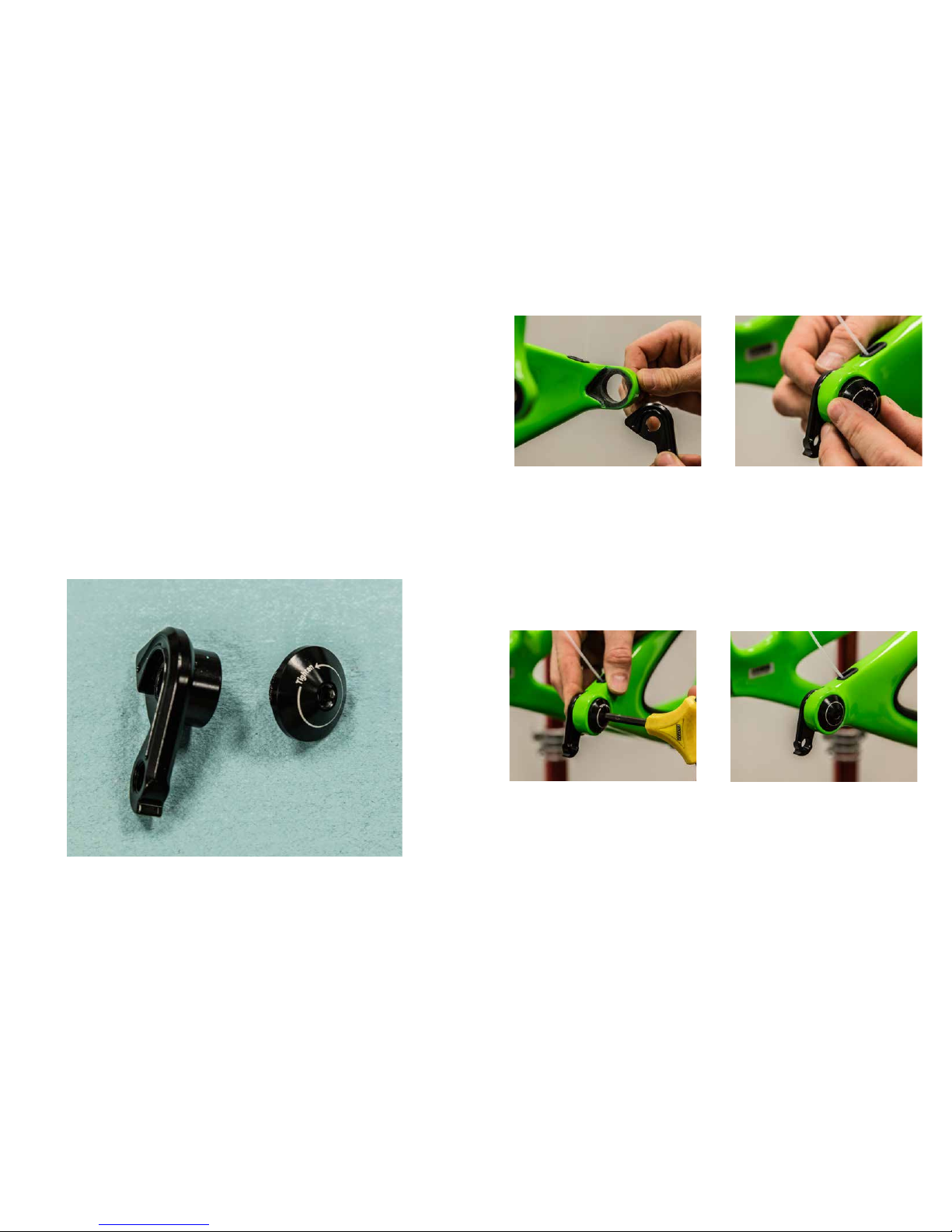
DERAILLEUR HANGER INSTALLATION
01. HANGER SEAT 02. HANGER CAP SEAT
Lightly grease the outside surface of the hanger
where it interfaces with the frame. The hanger
will t into its space on the inside of the swingarm
and presses easily into the frame.
Lightly grease the threasd on the hanger cap.
The hanger cap REVERSE threads into the
hanger from the outside of the swing arm. Hand
thread the cap into the hanger.
03. TIGHTENING 02. COMPLETED
Using a 6mm allen key, tighten the hanger cap
into the hanger. REMEMBER, it is REVERSE
THREADED. Follow the “Tighten” arrow on the
cap.
*Torque to 80 in/lbs (9Nm)
The installed hanger and cap should look like this,
sittign ush against the frame on both the inside
and outside of the swing arm. If the hanger
or cap are not sitting uch against the frame,
remove them and inspect the frame surfaces for
debris as well as the threads for damage.
NOTE: The hanger cap is REVERSE
THREADED. Be careful not to strip out the
Hanger tool faces. The cap is marked with a
tighten direction arrow.
Inspect the frame around the hanger seat for
any suspicious damage any time you replace
a hanger, but especially if you are replacing it
due to damage.
YETI TIPS TOOLS NEEDED
• 6mm Allen key
• Grease
DERAILLEUR HANGER INSTALL
18. 19.
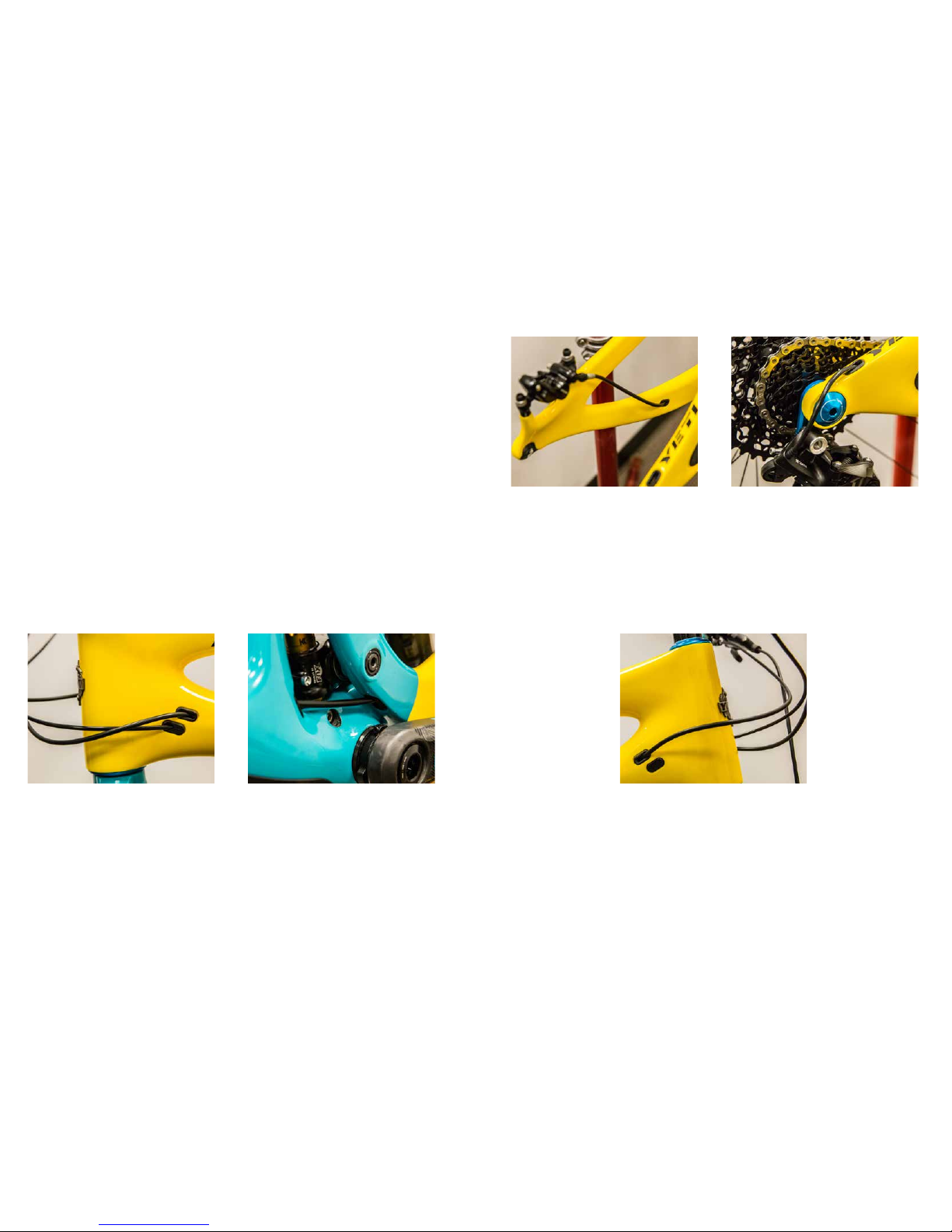
Your rear brake and shifter housing will run parallel around the left side of the head tube. From there you
will run those two into the housing ports on the non drive side of the head tube. The Rear shift housing and
brake housing exit the front triangle just above the Innity Link. The brake exiting on the non drive side, the
shift exiting on the drive side, both continuing into the coorispoding port on the swing arm.
*Use rubbiung alcohol to lubricate the housing. It will pass through the rubber grommets much easier.
*It may be easier in some cases to run the housing from the back of the bike up.
Caution: The failure to properly route shifter housing can cause malfunction of the shift mechanism and
unexpected shifting of gears.
The rear brake housing will exit the swing arm
via the port on the chainstay and go from there
directly to the brake caliper. If possible, adjust
the housing/caliper angle to give the housing the
cleanest, shortest route to the port.
CABLE HOUSING SETUP
The SB6c uses internally routed full length cable housing. By using full cable housing, we
have eliminated break points in the line of your shifter housing. This allows riders to experience
better overall shifting performance by reducing the entrance of unwanted elements such as
sweat and sediment. By routing that housing internally we add to the protection form the
elements and clean up the lines of the bike. No more zip ties to snag your shorts on and no
more loose housing rattling around on your paint.
Do not remove any of the housing guide tubes that are installed in your frame and swingarm.
They will be used to pull your housing through the frame. If you are replacing housing, use the
old housing to pull your new housing through the frame.
If you don’t have the tubes or old housig as a guide you can sh for it, but it will be easier to
get an internal routing tool.
REAR BRAKE AND DERAILLEUR ROUTING.
REAR BRAKE CONTINUED REAR DERAILLEUR CONTINUED
The rear shift housing exits the swing arm on
the top, just above the derailleur. Make sure
you leave enough slack in the housing to allow
for a smooth curve from the housing port to the
derailleur.
DROPPER POST
The dropper post housing will exit teh frame at
the upper port on the drive side of the head tube.
It is best to run the housing from the seatpost up
using either the guide provided with a new frame
or the previous housing. Without a guide, it can
be difcult to sh the housing into the downtube,
but it is possible.
20. 21.
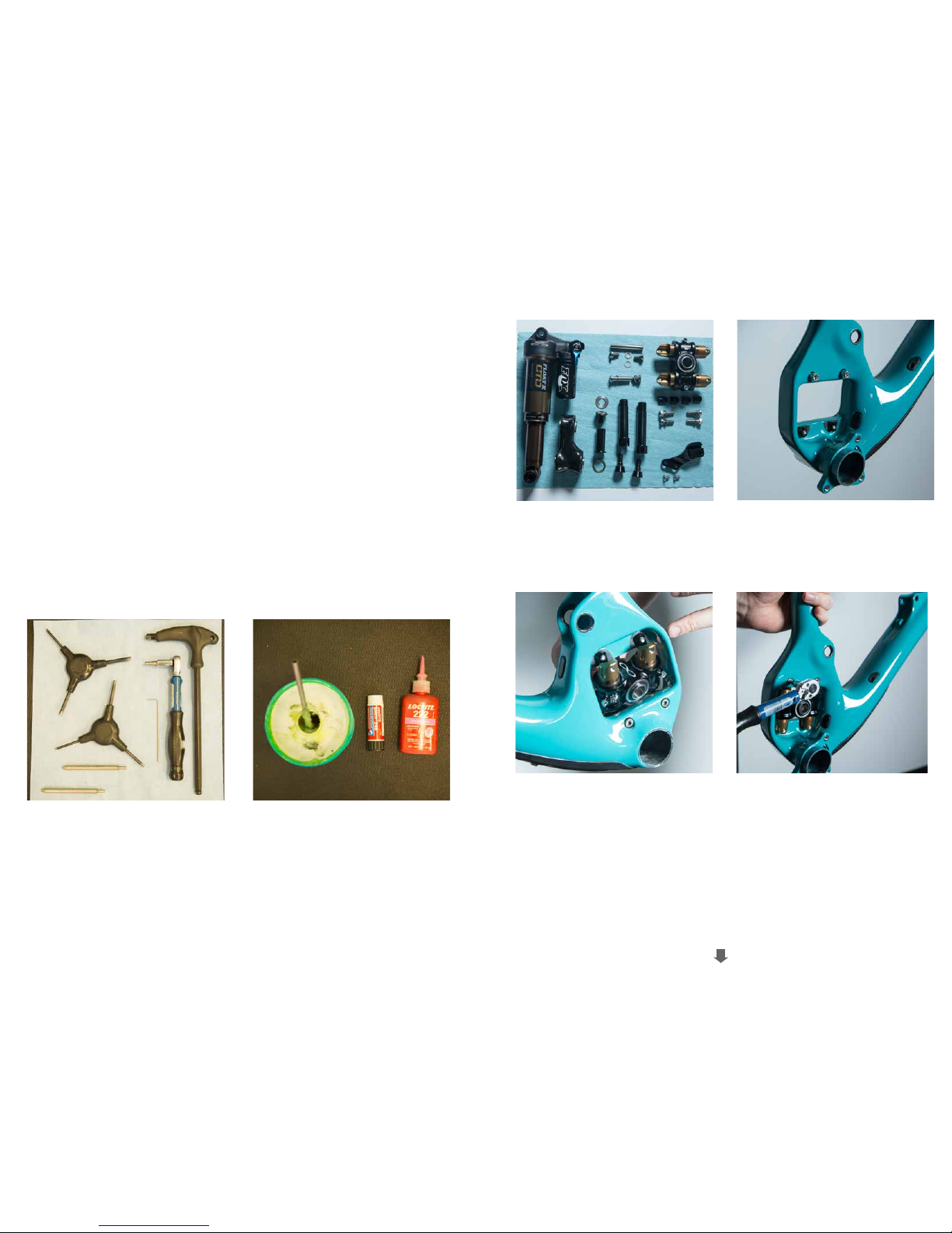
FRAME ASSEMBLY
Make sure your tools are in good condition.
A worn allen key can round the hex on a bolt
not allowing for proper torque.
Torque settings are listed throughout the
instructions. It is also import to prep all bolt
threads. The instructions denote whether to
use a Loctite compound or grease.
YETI TIPS TOOLS NEEDED
Warning: Service on Yeti bicycles requires special knowledge
and tools. Yeti Cycles recommends that all service and
repairs be performed by an authorized Yeti Dealer
• Dead blow hammer
• 2.5mm allen key
• Two - 5mm allen keys
• Two - 6mm allen keys
• 10mm allen key
• Guide pin tool
• Lock ring pliers
• Grease
• Blue (248) Loctite
• Pink (222) Loctite
• Torque wrench
All the parts you’ll need to get your SB6c put
together.
Slip washers onto and apply blue (248) Loctite to
the 4 bolts that secure the Switch Innity Link to
the frame. Insert them into their place and hang
the black Innity link tting washers from them.
Place them with the at side toward the opening.
Insert the Innity Link from the non-drive side.
The Innity logo should be up and the Fox logos
facing the non-drive side. Rock the link into
place capturing the black tting washers. Make
sure that they have not slipped or rotated. The
at end of the tting washers must be facing the
opening in the frame.
01. 02.
03. 04.
While holding the link in place lightly tighten the
bolts. You want them to snug so that the link
does not move and so that the tting washers
are fully captured, but don’t try to torque them by
hand! Finish the job with a torque wrench.
Torque to 12 Nm
Inhaltsverzeichnis
Andere Yeti Cycles Fahrradzubehör Handbücher


Beliebte Fahrradzubehör Handbücher anderer Marken

Sigma
Sigma BC 16.16 Bedienungsanleitung

Playcore
Playcore Dero Setbacks Bedienungsanleitung

VDO Cyclecomputing
VDO Cyclecomputing x3dw Bedienungsanleitung

Cateye
Cateye RAPID X2 Bedienungsanleitung

buratti meccanica
buratti meccanica Clorofilla Trail Bedienungsanleitung

Shimano
Shimano SG-8R20 Betriebsanleitung


