Zook RDI Bedienungsanleitung

www.zookdisk.com
Serving America, Central & South America
16809 Park Circle Drive, Chagrin Falls,
Ohio 44022 USA
Toll Free: +1 800 543 1043
Phone: +1 440 543 1010
E-mail: [email protected]
Serving Europe, Middle East & Africa
Navigation House, Bridge Street
Killamarsh, Sheffield,
S21 1AL UK
Phone: +44 (0) 1909 560999
E-mail: sales.europe@zookdisk.com
Serving Canada
4400 South Service Rd,
Burlington, Ontario L7L 5R8 CA
Toll Free: +1 800 370 6057
Phone: +1 905 681 2885
E-mail: sales.canada@zookdisk.com
Serving Asia Pacific
Unit No.23A-05, Menara Landmark, No.12,
Jalan Ngee Heng
80000 Johor Bahru, Johor, Malaysia
Phone: +60 (7) 2910099
E-mail: sales.asia@zookdisk.com
Page 1 of 2RDI_InstallationGuide_022219
Safety Through Knowledge and Performance
INSTALLATION INSTRUCTIONS
RDI Rupture Disk Indicator
SERVICE LIMITS
1. The RDI assembly can be used on liquid, gas or two phase flow.
2. Minimum System Operating Pressure:
1” to 2” 5 psig
3” to 2” 3 psig
6” and Up 1 psig
3. Operating Temperature Range: – 40°F (-40°C) to +392°F (200°C).
4. Suitable for intrinsically safe power levels. Maximum current 150mA, maximum voltage 24 Volts AC/DC.
WARNING: Use RDI assembly with intrinsically safe electrical device if used on any hazardous location. Consult
factory on services with fluids that are electrically conductive.
SELECT PROPER LOCATION
1. ALWAYS VENT THE OUTLET TO A SAFE AREA, away from personnel. If the process fluid is toxic or
hazardous connect the outlet side of the rupture disk assembly to a containment tank.
2. Consideration should be given to prevent build-up of rain water, snow, animal nesting or other debris that may
build up in the discharge piping and disturb the normal operation of the BAindicator.
3 If the RDI assembly is to be installed in a horizontal piping system DO NOT orient the RDI cable towards the
bottom. The recommended orientation is towards the top or either side.
INSTALLATION INSTRUCTIONS
1. The RDI assembly is installed on the vent side of the rupture disk assembly normally between the disk holder
and the companion flanges. The assembly is compatible with all ZOOK Graphite and Metal Rupture Disks and
holders. Sizes 1” – 24” are designed to fit within the bolts of standard ANSI class 150 flanges.
2. Clean the clamping surfaces of the companion flanges and if required the disk holder thoroughly.
3. The RDI assembly is NOT ‘Flow Direction’ sensitive. However, it is recommended that the “shiny” side of the
RDI is facing towards the rupture disk. Place the RDI assembly between the companion flange and diskholder
making sure it is centered and concentric with each other.
4. No additional gasket is required on the vent side of the rupture disk assembly. Process side gasket is required.
5. Mark the installation date on the RDI tag.
6. Follow the torquing procedure on next page.
7. Using approved Electrical Code Procedures connect the RDI to the burst detection circuit via the attached
cable.
LEAK DETECTION (LD) OPTION INSTALLATION
1. The LD is installed immediately upstream of the BA indicator.
2. Align outside diameter of LD with outside diameter ofthe BA.
3. The LD may be held in place by using small piece of Scotch® tape over the outside diameter on both sides of
the BA. Locate tape 90° from both sides of identification tag.
Tape must not extend more than half way across gasket surface.
After each leak detection a replacement LD must be installed. Contact ZOOK for replacement LD kits.
www.zookdisk.com
Serving America, Central & South America
16809 Park Circle Drive, Chagrin Falls,
Ohio 44022 USA
Toll Free: +1 800 543 1043
Phone: +1 440 543 1010
E-mail: [email protected]
Serving Europe, Middle East & Africa
Navigation House, Bridge Street
Killamarsh, Sheffield,
S21 1AL UK
Phone: +44 (0) 1909 560999
E-mail: sales.europe@zookdisk.com
Serving Canada
4400 South Service Rd,
Burlington, Ontario L7L 5R8 CA
Toll Free: +1 800 370 6057
Phone: +1 905 681 2885
E-mail: sales.canada@zookdisk.com
Serving Asia Pacific
Unit No.23A-05, Menara Landmark, No.12,
Jalan Ngee Heng
80000 Johor Bahru, Johor, Malaysia
Phone: +60 (7) 2910099
E-mail: sales.asia@zookdisk.com
Page 2 of 2RDI_InstallationGuide_022219
Safety Through Knowledge and Performance
INSTALLATION INSTRUCTIONS
RDI Rupture Disk Indicator
TORQUING PROCEDURE
1. Finger tighten all of the nuts.
2. Using a torque wrench, cross-tighten each bolt to ¼ of the desired final torque (see table 1 below) until every
bolt has been tightened.
3. Repeat step 2 to ½, ¾, and then to the full desired final torque.
NOTE: OVER TORQUING CAN DAMAGE THE BA INDICATOR.
Warning: Field modification and material substitution will void the warranty of this product.
WARRANTY
ZOOK warrants its products against Defective workmanship and materials. This Warranty is limited to the replacement
without charge of the defective product only and does not cover any other direct or indirect costs which may be
attributed to the defect, provided It is properly installed and used within the scope for which it is intended.
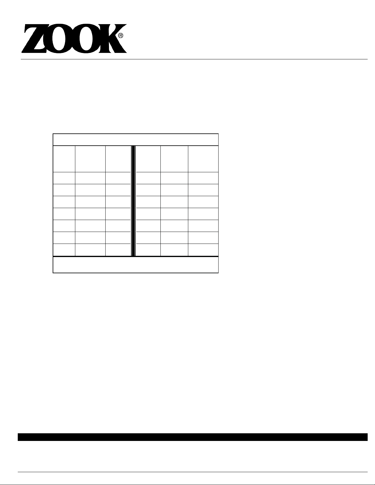
Table 1 – Recommended Torque Values
Size
ANSI
Flange
Class
Torque
(ft. lbs.)
Size ANSI
Flange
Class
Torque
(ft. lbs.)
1”
150
10 10” 150 55
1 ½”
150
20 12” 150 70
2”
150
35 14” 150 100
3”
150
45 16” 150 80
4”
150
35 18” 150 110
6”
150
60 20” 150 100
8”
150
70 24” 150 150
TORQUE VALUES BASED ON THE THREADS BEING LIGHTLY
LUBRICATED AND FREE RUNNING
Inhaltsverzeichnis


