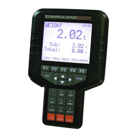
COMPULOAD CL2000MKII Gebrauchs- und Pflegehandbuch

1
BASIC INSTALLATION, CALIBRATION and OPERATING INSTRUCTIONS
for the COMPULOAD CL2000MKII Series LOAD WEIGHING SYSTEM
For forklift or small loader application
Instant Weight Pty. Ltd.
P.O. Box 2340
MIDLAND WA 6936
Tel: (08) 9274 8600
Email: sales@instantweighing.com.au

2
INDEX
Introduction
Installation Instructions
Basic Calibration
Basic Weighing
WARRANTY

3
Introduction
The CL2000MKII Weighing Indicator IP65 rated digital indicator designed
for use on forklifts and small wheel loaders.
Operating Voltage is 12-24Volts DC
The CL2000MKII will generally be installed with a Hydraulic pressure
transducer mounted in the Lift Circuit of the machine hydraulics. The
hydraulic transducer should be mounted in an area that is not affected by
high pressure cleaning.

4
INSTALLATION PROCEDURE FOR THE COMPULOAD CL2000MKII
NOTE: - These basic installation instructions are given based
on the installer having previous experience in the servicing and
maintenance of machinery. General safety precautions should
be undertaken similar to carrying out maintenance on this type
of machinery. Inexperienced personnel should not undertake
this task if they are unsure of the safety precautions necessary.
*FITTING THE COMPULOAD TO THE OPERATORS CABIN
Select a suitable location and using the mounting bracket as a
template, drill two holes and mount the bracket into position.
Allow room for the cable at the rear of the instrument
DO NOT DRILL OR WELD ONTO ANY PORTION OF A
R.O.P.S. or F.O.P.S
A bracket however can be bolted onto a lock striker plate, window
frame aperture or turret support. Consider wiring and cabling
when choosing a mounting position. Consideration should also
be given so the instrument does not impede operator vision.
Vibration should also be taken into account so as not to damage
the machine

5
FITTING THE PRESSURE TRANSDUCER
PRECAUTIONS
Lower load carriage completely to the ground and stop the
engine.
Operate the tilt and lift levers to ensure no residual pressure
is present in the hydraulic system.
Remove the hydraulic tank filler cap to remove any pressure
from the oil reservoir tank.
Slightly loosen any “easy to get at” fitting in the lifting circuit to
ensure no pressure is present. The transducer is to be fitted into the
lifting circuit of the hydraulic system between the control valve and the
lifting cylinders. If possible, use a hydraulic adaptor fitting that can be
installed into the system allowing a “take off” point. Failing this, the
system will have to be entered by direct drilling and tapping into a
suitable hydraulic connection. Ensure the suitable hydraulic
connection (tee piece, elbow or similar) is removed from the forklift
before drilling and tapping. Enter the system by drilling (8.2mm) and
tapping (1/8 BSPT). Ensure all swarf is removed and refit to machine.
Connect appropriate fitting and hose to allow transducer to be
mounted in a safe position. Avoid areas that are subject to oil and
water. Do not run cable through articulated or moving areas of the
machine. Ensure the hose does not foul when machine is operated.
Connect the transducer to the hydraulic line. Tighten the fittings. Start
the motor and lift the forklift carriage approx 10mm from the ground.
Bleed the air from the line, then using spanners, retighten the
transducer.

6
Transducer connector instructional video.
Transducer Connector Diagram
Transducer
Green

7
WIRING THE CL2000MKII to the Forklift or Loader –
The CL2000MKII fits machines that have 12-24Vdc power supply.
Voltages other than this may require a voltage reducer.
BROWN = Power either battery or ignition
WHITE = Earth
Wiring the Compuload CL4070 Printer (if fitted) –
The Compuload CL4070 Printer can be wired to the CL2000MKII by
the 3-core wire coming from the rear of the CL2000MKII plug. This
wire should be marked “printer”.
Brown = Power
White = Earth
Green = TXD
ESTABLISHING A WEIGHING POINT (Static mode)
When weighing in the static method a predetermined weighing point
must be established. The weighing point on a standard forklift is
usually about one meter from ground. For a Loader is when the loader
arms are approx horizontal.
The weighing point is identified by either -
a). Applying stickers to the mast or loader arms (stickers usually
supplied in kit)
b) Welding a pointer to the mast or loader arms identifying the position.
All reference to “Weighing Position” in any instructions means
lifting the forks or bucket to position 1 and lowering slowly to

8
position 2. When lowering to position 2, this must be done
smoothly and slowly to allow the hydraulic pressure to be
consistent. Lowering abruptly will cause a pressure spike within
the lift circuit and readings will be erratic.

9
BASIC CALIBRATION INSTRUCTIONS
The calibration instructions below are given, based on the instrument being set
up prior to being shipped to you. The instrument will have been set up based
on the information supplied regarding the model, capacity and application the
forklift is being used.
This instrument can be used in a large variety of applications and changing the
parameters that are set will greatly affect the performance of this instrument in
the application you have indicated.
NOTE- To exit the calibration mode without saving, turn the power off to the
indicator.
Step 1. –Ensure you have an accurate test weight of approx 1/3 –½ of the
machine capacity. The more accurate the test weight, the more accurate the
scale
Step 2 –Start the forklift or loader, and the CL2000MKII should also turn on.
The indicator should power up and go through a short power up cycle. Once
the power up cycle finishes, the indicator will show a random reading in the
“Current Load” screen. To ensure you have the hydraulic pressure transducer
fitted correctly, raising of the forks or bucket should result in the figure on the
screen rising.
Step 3- Press the “Menu” button on the bottom right-hand corner of the screen
to enter the Menu screen.
Step 4 –Press the “Calibration” to enter the setup code. Enter the code 4482
using the up, down, left, right arrows. Then Press the “Exit” button. You will
now be in the Calibration Page. Press “Weighing Calibration” to enter the
Weighing Calibration page.
Step 5 –Raise the empty Forks or Bucket to your weighing height. (Raise to 1,
Lower to 2) Allow approx 2-3 seconds for the weight to settle, Press “Set
Empty Calibration”on the screen to set the Zero Calibration
Step6 –Place your test weight onto the forks or bucket. Don’t lift to weighing
height at this stage. Enter the test weight amount to “Known Load” using the
Up, Down keys.

10
Step7- It is now time to pick up the test weight and raise to the weighing height
, (Raise to 1 , Lower to 2) . Allow approx 2-3 seconds for the weight to settle,
and then press the “Set Laden Calibration” key once.
Step8- Check the “Calculated Current Weight” screen to see if the weight
displays the test weight figure. If not, you may need to reset the Zero, Step 5,
and the Test Weight again.
Step 9 –Press the “Exit” button one press at a time to return to the main
weighing page and to save the calibration.
Perform as many test weighings until you are satisfied the system is working
correctly.
If at any time the indicator indicates an error message during the calibration
process, call your supplier for assistance. Before calling check that the
hydraulics have been installed into the correct ‘LIFT’ circuit of the machine,
and also check that your test weight is at least 1/3 - ½ machine capacity.
Inhaltsverzeichnis
Andere COMPULOAD Zubehör Handbücher