
Dynamica VELOCITY 13u Bedienungsanleitung

VELOCITY 13µ
Minifuge
Operation Manual
Model Velocity 13µ
Revision : D01- V1.01


1
CONTENTS
Page #
1. Meanings of Symbols & Safety Precautions .................................................................................. 2
1-1. Meanings of Symbols ................................................................................................................. 2
1-2. Safety Precautions ..................................................................................................................... 3
2. Product Description and Technical Specifications ....................................................................... 5
2-1. Product Description .................................................................................................................... 5
2-2. Technical Specifications ............................................................................................................ 6
3. Installation ...................................................................................................................................... 7
3-1. Power on/off................................................................................................................................. 7
3-2. Rotor coupling and disassembling............................................................................................... 8
3-3. Positioning of Sample Tubes....................................................................................................... 9
4. Operation ...................................................................................................................................... 10
4-1. Key Functions of Control Panel ............................................................................................... 10
4-2. Setting RPM/RCF ...................................................................................................................... 11
4-3. Setting Time............................................................................................................................... 12
4-4. Start/Stop ................................................................................................................................... 12
4-5. Pulse .......................................................................................................................................... 13
4-6. Emergency door open ............................................................................................................... 13
5. Maintenance ................................................................................................................................. 14
5-1. Outer part of instrument ........................................................................................................... 14
5-2. Chamber .................................................................................................................................. 14
5-3. Shaft ......................................................................................................................................... 14
5-4. Rotor ........................................................................................................................................ 14
5-5. Transportation of the instrument................................................................................................ 14
6. Trouble Shooting ........................................................................................................................ 14
6-1. Check list .................................................................................................................................. 14
6-2. Error Code ................................................................................................................................. 16
7. Rotors & Accessories ................................................................................................................... 17
2
1. Meanings of Symbols & Safety Precautions
1-1. Meanings of Symbols
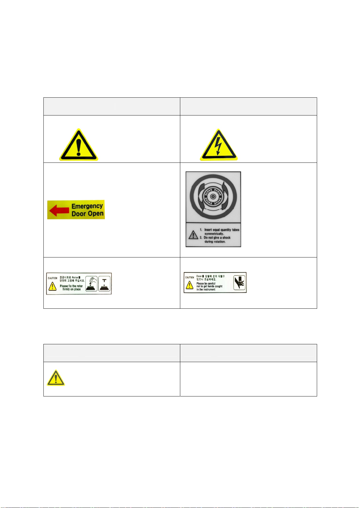
1-1-1. Symbols on the device
Symbol Meaning Symbol Meaning
Attention and warning.
Attention and warning
for an electric shock
Indicate a hole for door
opening in case of
emergency
Attention and warning
for correct way of
sample balancing in
the rotor.
Attention and warning
for rotor coupling.
Attention and warning
for door opening and
closing
1-1-2. Symbols in this document
Symbol Meaning Symbol Meaning
This symbol refers to safety
relevant warnings and indicates
possible dangerous outcomes.
☞Note.
This symbol refers to the important
reminder.
1-2. Safety Precautions
Before using the instrument, please read this operation manual to ensure correct usage through
understanding. Incorrect handling of the instrument could possibly result in personal injury or physical
damage on the instrument or its accessories.

3
1. ALWAYS locate the instrument on a flat, rigid and stable table capable of withstanding the
weight of the instrument and its spinning operation.
2. ALWAYS make a safety zone of 30 cm around the centrifuge to indicate that neither
hazardous materials nor persons should be permitted within the area during operation.
9ALWAYS position the instrument with enough space on each side of instrument to
ensure proper air circulation.
3. ALWAYS install the instrument within a temperature and humidity controlled environment.
(Permissible ambient temperature: +5°C – +35 °C, Relative humidity: ≤85%)
4. Should not use a power source other than the instrument designed to operate on.
5. Should not use unapproved rotors and associated components.
9Only use rotors from Dynamica with appropriate centrifugal tubes and suitable
adaptors to embrace sample containers tightly enough inside rotors.
6. Before operating the instrument, check if the rotor and the rotor lid are securely fastened.
9Should operate the instrument with a rotor properly installed and secured to the
motor shaft.
7. Mount the rotor on the motor shaft properly, check it with spinning manually.
8. Do not stop the rotor by touching with hand during the instrument is running.
9. Emergency door open should be performed only when spinning is completely stopped.
10. Should not exceed the rated speed or specific gravity. Samples whose density is greater than
1.2g/ml must have reduced maximum rotational speed to avoid rotor failure.
11. The sample content should not exceed 80% of total capacity of a tube. Otherwise, it would
cause spillage of sample fluid and even the tube breakage.
12. ALWAYS load the tubes symmetrically with evenly weighted samples to avoid rotor
imbalance. If necessary, use the water blank to counterbalance the unpaired sample.
13. The operation speed should not exceed the lowest value of the individual guaranteed g-
forces among the centrifuge, rotor, bucket or adaptors and sample container, especially the
guaranteed g-force of sample container should not be neglected.
14. The rotors should be cleaned and kept dry after every use for longer life time and safety.
15. ALWAYS disconnect the power supply prior to maintenance and servicing to avoid electrical
shock.
16. ALWAYS use proven disinfection procedures after centrifuging biohazardous materials.
17. Should not centrifuge flammable, toxic, radioactive, explosive, or corrosive materials.

4
18. When it is necessary to use toxic or radioactive materials or pathogenic micro-organisms
which belong to the Risk Group II of WHO: “Laboratory Bio- safety Manual,” should follow
national regulations.
9Do not place dangerous materials within 30cm distance around the instrument,
and that is also recommended by IEC 61010-2-020.
9Use the emergency door open function only when the door button on the control
panel is dumb under the condition of complete stop of rotor running.
9Never try to open or move the instrument if it is not completely stopped.
9If the power input is more than +/- 10% of the recommended voltage or fluctuates
frequently, it may cause malfunction of the instrument and often result serious
damage.
9Install the instrument at the place without any kinds of corrosive gases.
5
2. Product Description & Technical Specifications
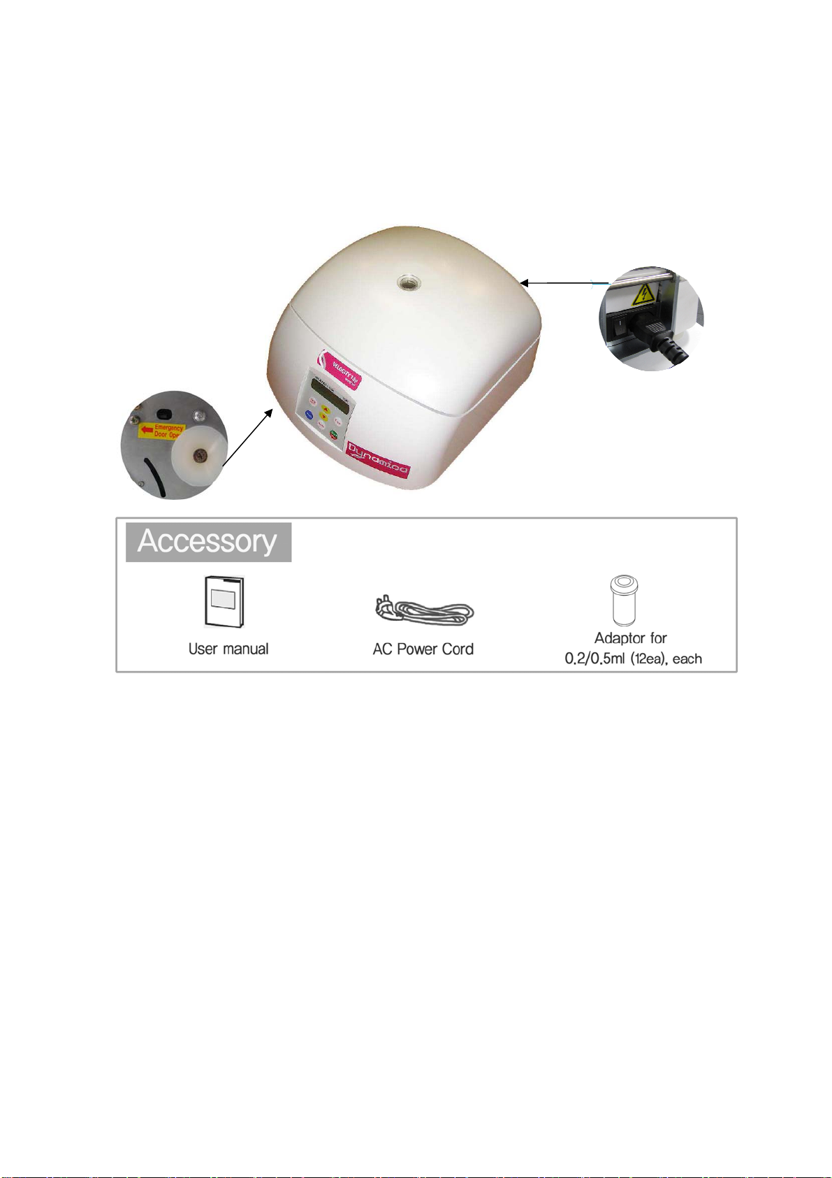
2-1. Product Description
¾Velocity 13μincludes Fixed Angle rotor FA13A and 12 of 0.2ml & 0.5ml adaptors.
¾The PCR tube rotor is optional.
Emergency Door open
Power supply

6
2-2. Technical Specifications
Max. RPM/RCF 13,500 rpm/ 12,300 xg
FA13A
6,000 rpm/ 1,850 xg
FA6B
Max. capacity 12 x 2.0 ml tubes 4 x 8-tube PCR strips
Time control Pulse or timed ≤30 min
RPM/RCF conversion Yes
Noise level(dB) ≤56
Acc/Dec(sec) ≤12 / < 16
Display Blue LCD
Automatic door release at completion Yes
Power supply(V/Hz) 220/50~60 (110V optional)
Power requirement(VA) 110 Watts
Dimension(W x D x H, mm) 208 x 245 x 145
Weight without rotor (Kg) 4.4
CE mark Yes

7
3. Installation
3-1. Power On/off and Door Release
3-1-1. Power On/off
Action
1. Connect the AC Power cord at the power socket on the back
of the instrument.
2. Turn on the instrument by pressing a switch on the back
of the instrument.
3. Press the ‘Door’ button to open the door.
3-1-2. Door Release
Action
1. For opening the door, press the [DOOR] button.
¾The door is automatically opened after
completion of spinning operation with
beeping sound.
¾When you close the door, close it until
hearing clank shut.
☞
9The door is not opened while the instrument is running.
9If the door is opened, the instrument could not operate even with pressing the ‘Start’
button.
9Power Failure: If there is any power failure during the operation, door is not opened
with ‘Door’ button. Door can be opened only when the operation is completely
stopped and the power is on again. If you want to open the door at the power failure,
please refer to ‘4-6. Emergency Door Open’.
3-2. Rotor coupling and disassembling
Action
1. Before coupling a rotor, clean the motor shaft and chamber with soft dry
towel.
2. Mount a proper rotor into the motor shaft.
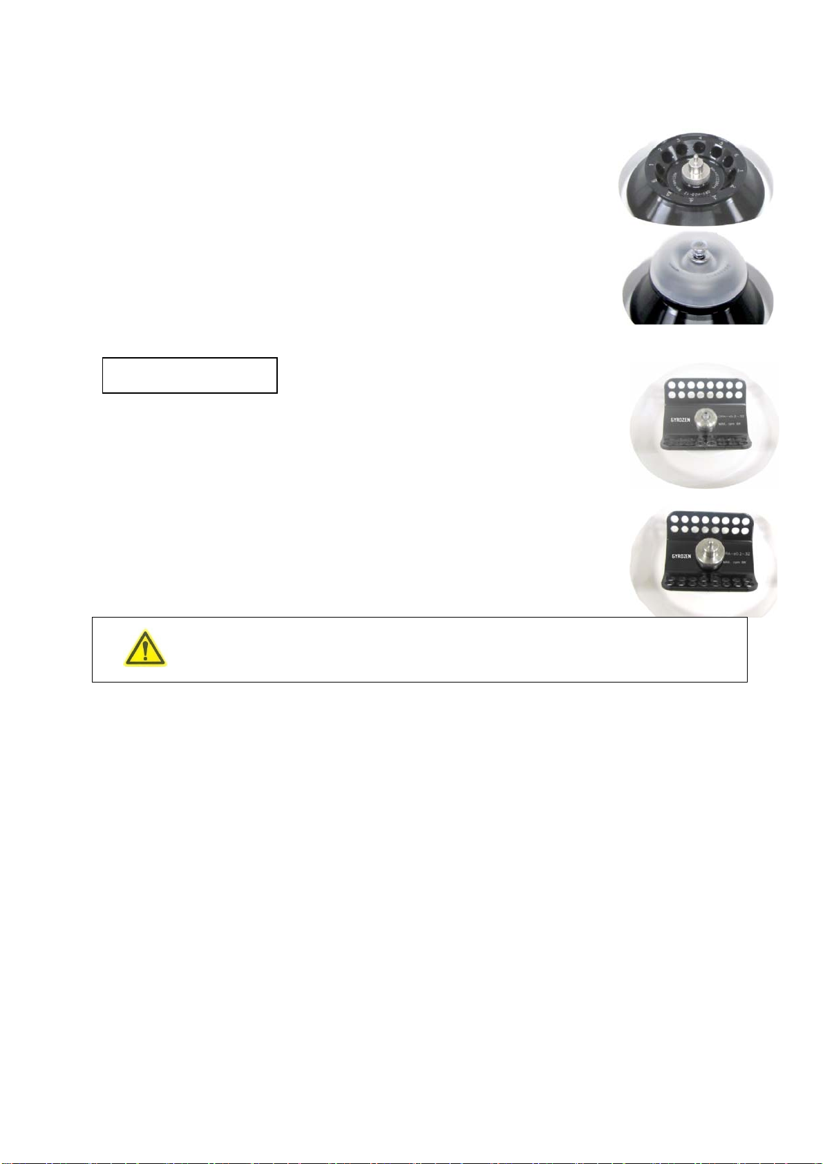
Fixed Angle Rotor
8
3. Place the Rotor Locking Nut at the center hole of the rotor.
¾To assemble the rotor: Rotate the Rotor Locking Nut clockwise
until tightly assembled.
¾To disassemble the rotor: Rotate the Rotor Locking Nut
counterclockwise.
4. After loading sample tubes, close the rotor lid until hearing clank shut.
¾When you open the lid, lift the nut.
2. Mount the PCR rotor into the motor shaft.
3. Place the Rotor Locking Nut at the center hole of rotor.
¾To assemble the rotor: Rotate the Rotor Locking Nut clockwise
until tightly assembled.
¾To disassemble the rotor: Rotate the Rotor Locking Nut
counterclockwise.
9When the PCR rotor is coupled, please do not speed over 6,000rpm/2,400
rcf.
3-3. Positioning of Sample Tubes
Action
1. Before loading sample tubes, check the water drop or dirt in the rotor hole or inner adaptor.
¾If there is a water drop or dirt in the rotor hole or inner adaptor, remove it with soft
dry cloth.
2. Tubes should be placed in the rotor with same amount of samples and symmetrical positions.
¾Only use appropriate centrifugal tubes and do not exceed the speed beyond the
tube’s max g-force.
¾For safety, fill the sample for 70~80% in the tubes.
PCR Rotor
Inhaltsverzeichnis
Andere Dynamica Laborausrüstung Handbücher


Beliebte Laborausrüstung Handbücher anderer Marken


Agilent Technologies
Agilent Technologies 5800 ICP-OES Bedienungsanleitung

Endress+Hauser
Endress+Hauser Cleanfit CPA875 Bedienungsanleitung

NI
NI PXI-5422 Handbuch

Collomix
Collomix Aqix Bedienungsanleitung

SPEX SamplePrep
SPEX SamplePrep 6875 Freezer/Mill Series Bedienungsanleitung

Ocean Insight
Ocean Insight FLAME-NIR+ Bedienungsanleitung

Parker
Parker ALIGN-MG-NA Bedienungsanleitung

BD
BD 644787 Bedienungsanleitung

DENTAURUM
DENTAURUM Compact Megaplus Bedienungsanleitung

Biuged Laboratory Instruments
Biuged Laboratory Instruments BGD 626 Bedienungsanleitung

VWR
VWR SAS Super IAQ Bedienungsanleitung

illumina
illumina MiSeqDx Bedienungsanleitung