ETAS CBS100.1-2 Bedienungsanleitung

www.etas.com
CBS100.1-2 / CBS104.1-2 / CBS105.1-2
Smart Lambda Sensor Cable
User‘s Guide

Copyright
The data in this document may not be altered or amended without special noti-
fication from ETAS GmbH. ETAS GmbH undertakes no further obligation in
relation to this document. The software described in it can only be used if the
customer is in possession of a general license agreement or single license.
Using and copying is only allowed in concurrence with the specifications stipu-
lated in the contract.
Under no circumstances may any part of this document be copied, reproduced,
transmitted, stored in a retrieval system or translated into another language
without the express written permission of ETAS GmbH.
© Copyright 2019 ETAS GmbH, Stuttgart
The names and designations used in this document are trademarks or brands
belonging to the respective owners.
CBS10x.1-2 - User’s Guide R12 EN - 06.2019

ETAS Contents
Contents
CBS10x.1-2 - User’s Guide 3
1 General . . . . . . . . . . . . . . . . . . . . . . . . . . . . . . . . . . . . . . . . . . . . . . . . . . . . . . . . . . . . . . 5
1.1 About this Manual . . . . . . . . . . . . . . . . . . . . . . . . . . . . . . . . . . . . . . . . . . . . . . . . . . . . . . . . 5
1.2 Basic Safety Notices . . . . . . . . . . . . . . . . . . . . . . . . . . . . . . . . . . . . . . . . . . . . . . . . . . . . . . 6
1.2.1 Identification of Safety Notices . . . . . . . . . . . . . . . . . . . . . . . . . . . . . . . . . . . . 6
1.2.2 General Safety Information . . . . . . . . . . . . . . . . . . . . . . . . . . . . . . . . . . . . . . . 6
1.2.3 Requirements for Users and Duties for Operators. . . . . . . . . . . . . . . . . . . . 7
1.2.4 Intended Use . . . . . . . . . . . . . . . . . . . . . . . . . . . . . . . . . . . . . . . . . . . . . . . . . . . . 7
1.3 Identifications on the Product . . . . . . . . . . . . . . . . . . . . . . . . . . . . . . . . . . . . . . . . . . . . . . 9
1.4 RoHS Conformity. . . . . . . . . . . . . . . . . . . . . . . . . . . . . . . . . . . . . . . . . . . . . . . . . . . . . . . . 10
1.4.1 European Union . . . . . . . . . . . . . . . . . . . . . . . . . . . . . . . . . . . . . . . . . . . . . . . . 10
1.4.2 China. . . . . . . . . . . . . . . . . . . . . . . . . . . . . . . . . . . . . . . . . . . . . . . . . . . . . . . . . . 10
1.5 CE Marking . . . . . . . . . . . . . . . . . . . . . . . . . . . . . . . . . . . . . . . . . . . . . . . . . . . . . . . . . . . . . 10
1.6 Product Return and Recycling. . . . . . . . . . . . . . . . . . . . . . . . . . . . . . . . . . . . . . . . . . . . . 10
2 Hardware Description . . . . . . . . . . . . . . . . . . . . . . . . . . . . . . . . . . . . . . . . . . . . . . . . 11
2.1 Overview . . . . . . . . . . . . . . . . . . . . . . . . . . . . . . . . . . . . . . . . . . . . . . . . . . . . . . . . . . . . . . . 11
2.1.1 Products and Application Areas . . . . . . . . . . . . . . . . . . . . . . . . . . . . . . . . . . 11
2.1.2 Properties . . . . . . . . . . . . . . . . . . . . . . . . . . . . . . . . . . . . . . . . . . . . . . . . . . . . . 12
2.2 Design of the Smart Lambda Sensor Cable . . . . . . . . . . . . . . . . . . . . . . . . . . . . . . . . . 13
2.2.1 "LAMBDA" Connection with RB150 Coupling (Code 1) . . . . . . . . . . . . . . . 13
2.2.2 Electronic Module . . . . . . . . . . . . . . . . . . . . . . . . . . . . . . . . . . . . . . . . . . . . . . 13
2.2.3 Inputs and Outputs (Open Cable End) . . . . . . . . . . . . . . . . . . . . . . . . . . . . . 14
2.2.4 Connections "AOUT" and "AOUT_GND" . . . . . . . . . . . . . . . . . . . . . . . . . . . . 14
2.2.5 "CONFIG" Connection (Configuration Input) . . . . . . . . . . . . . . . . . . . . . . . . 16
2.2.6 "ERROR" Connection (Error Output) . . . . . . . . . . . . . . . . . . . . . . . . . . . . . . . 16
2.2.7 Connections "AC1" and "AC2" (Voltage Supply) . . . . . . . . . . . . . . . . . . . . . 17
3 Commissioning . . . . . . . . . . . . . . . . . . . . . . . . . . . . . . . . . . . . . . . . . . . . . . . . . . . . . 18
3.1 General Recommendations for Installation and Operation . . . . . . . . . . . . . . . . . . . . 18
3.1.1 Lambda Sensor Cable. . . . . . . . . . . . . . . . . . . . . . . . . . . . . . . . . . . . . . . . . . . 18
3.1.2 Lambda Sensor . . . . . . . . . . . . . . . . . . . . . . . . . . . . . . . . . . . . . . . . . . . . . . . . 19
3.2 Startup Sequence . . . . . . . . . . . . . . . . . . . . . . . . . . . . . . . . . . . . . . . . . . . . . . . . . . . . . . . 19
3.3 Assembly of the Lambda Sensor . . . . . . . . . . . . . . . . . . . . . . . . . . . . . . . . . . . . . . . . . . 19
3.3.1 Technical Information . . . . . . . . . . . . . . . . . . . . . . . . . . . . . . . . . . . . . . . . . . 19
3.3.2 Notes about Installing the Lambda Sensor. . . . . . . . . . . . . . . . . . . . . . . . . 20
3.3.3 Assembly of the Bosch Lambda Sensor . . . . . . . . . . . . . . . . . . . . . . . . . . . 21
3.4 Cabling. . . . . . . . . . . . . . . . . . . . . . . . . . . . . . . . . . . . . . . . . . . . . . . . . . . . . . . . . . . . . . . . . 22
3.4.1 "LAMBDA" Connection (Lambda Sensor) . . . . . . . . . . . . . . . . . . . . . . . . . . 22
3.4.2 "AOUT" Connection (Analog Output). . . . . . . . . . . . . . . . . . . . . . . . . . . . . . . 22
3.4.3 "CONFIG" Connection (Configuration Input) . . . . . . . . . . . . . . . . . . . . . . . . 23
3.4.4 "ERROR" Connection (Error Output) . . . . . . . . . . . . . . . . . . . . . . . . . . . . . . . 23
3.4.5 Connections "AC1" and "AC2" (Voltage Supply) . . . . . . . . . . . . . . . . . . . . . 24
4 Technical Data . . . . . . . . . . . . . . . . . . . . . . . . . . . . . . . . . . . . . . . . . . . . . . . . . . . . . . 25
4.1 General Data . . . . . . . . . . . . . . . . . . . . . . . . . . . . . . . . . . . . . . . . . . . . . . . . . . . . . . . . . . . . 25
4.1.1 Standards . . . . . . . . . . . . . . . . . . . . . . . . . . . . . . . . . . . . . . . . . . . . . . . . . . . . . 25
4.1.2 Ambient Conditions . . . . . . . . . . . . . . . . . . . . . . . . . . . . . . . . . . . . . . . . . . . . 25
4.2 Mechanical Data . . . . . . . . . . . . . . . . . . . . . . . . . . . . . . . . . . . . . . . . . . . . . . . . . . . . . . . . 26

ETAS Contents
CBS10x.1-2 - User’s Guide 4
4.2.1 Dimensions and Weight . . . . . . . . . . . . . . . . . . . . . . . . . . . . . . . . . . . . . . . . . 26
4.2.2 Connections of the Lambda Sensor Cable . . . . . . . . . . . . . . . . . . . . . . . . . 26
4.2.3 "LAMBDA" Connection with RB150 Coupling (part 1 in Fig. 4-2). . . . . . . 27
4.2.4 Open Cable End with Ferrules (part 2 in Fig. 4-2). . . . . . . . . . . . . . . . . . . . 27
4.3 Electrical Data. . . . . . . . . . . . . . . . . . . . . . . . . . . . . . . . . . . . . . . . . . . . . . . . . . . . . . . . . . . 28
4.3.1 Voltage Supply . . . . . . . . . . . . . . . . . . . . . . . . . . . . . . . . . . . . . . . . . . . . . . . . 28
4.3.2 Startup Behavior during Normal Startup of the Supply Voltage . . . . . . . 28
4.3.3 "LAMBDA" Connection with RB150 Coupling . . . . . . . . . . . . . . . . . . . . . . 29
4.3.4 Configuration Input ("CONFIG" Connection) . . . . . . . . . . . . . . . . . . . . . . . . 29
4.3.5 Error Output ("ERROR" Connection) . . . . . . . . . . . . . . . . . . . . . . . . . . . . . . . 30
4.3.6 "AOUT" Connection ("AOUT" Analog Output). . . . . . . . . . . . . . . . . . . . . . . . 30
4.3.7 CBS100.1-2: Measure Ranges and Graduation . . . . . . . . . . . . . . . . . . . . . 32
4.3.8 CBS104.1-2: Measure Range and Graduation . . . . . . . . . . . . . . . . . . . . . . 33
4.3.9 CBS105.1-2: Measure Ranges and Graduation . . . . . . . . . . . . . . . . . . . . . 34
5 Ordering Information . . . . . . . . . . . . . . . . . . . . . . . . . . . . . . . . . . . . . . . . . . . . . . . . . 36
6 ETAS Contact Addresses . . . . . . . . . . . . . . . . . . . . . . . . . . . . . . . . . . . . . . . . . . . . . 37
Figures . . . . . . . . . . . . . . . . . . . . . . . . . . . . . . . . . . . . . . . . . . . . . . . . . . . . . . . . . . . . 38
Index . . . . . . . . . . . . . . . . . . . . . . . . . . . . . . . . . . . . . . . . . . . . . . . . . . . . . . . . . . . . . . 39

ETAS General
CBS10x.1-2 - User’s Guide 5
1 General
This chapter contains information about the following topics:
• “About this Manual” on page 5
• “Basic Safety Notices” on page 6
• “Identifications on the Product” on page 9
• “RoHS Conformity” on page 10
• “CE Marking” on page 10
• “Product Return and Recycling” on page 10
1.1 About this Manual
Representation of information
All activities to be performed by the user are presented in a "Use Case" format.
That is, the goal to be accomplished is briefly defined in the heading, and the
respective steps required for reaching this goal are then presented in a list. The
presentation looks as follows:
Goal definition:
Any preliminary information...
1. Step 1
Any explanations for step 1...
2. Step 2
Any explanations for step 2...
3. Step 3
Any explanations for step 3...
Any concluding comments...
Typographical conventions
The following typographical conventions are used:
Important notes for the user are presented as follows:
Click on OK. Button labels are printed in bold charac-
ters.
Press <ENTER>. Keyboard commands are presented in
angled brackets starting with capital let-
ter.
The "File Open" dialog appears. Names of program windows, dialog win-
dows, fields and similar are given in quo-
tation marks.
Bold Labels of the device
Italic Particularly important text passages
TIP
Important note for the user.

ETAS General
CBS10x.1-2 - User’s Guide 6
1.2 Basic Safety Notices
1.2.1 Identification of Safety Notices
The safety notices contained in this manual are identified with the danger sym-
bol shown below:
The safety notices shown below are used for this purpose. They provide notes
to extremely important information. Please read this information very carefully.
1.2.2 General Safety Information
Please observe the Product safety notices for the product ("Safety Advice
Smart Lambda Sensor Cable CBS10x.x") and the following safety notices to
avoid any effects on your health or damages to the device.
ETAS GmbH does not assume any liability for damages resulting from
improper handling, unintended use or non-observance of the safety precau-
tions.
DANGER
indicates an immediate danger with a high risk of death or serious injury, if
not avoided.
WARNING
indicates a possible danger with moderate risk of death or (serious) injury, if
not avoided.
CAUTION
identifies a hazard with low risk that could result in minor or medium physical
injuries or property damages if not avoided.
TIP
Carefully read the documentation that belongs to the product prior to the
startup.

ETAS General
CBS10x.1-2 - User’s Guide 7
1.2.3 Requirements for Users and Duties for Operators
The product may be assembled, operated and maintained only if you have the
necessary qualification and experience for this product. Improper use or use by
a user without sufficient qualification can lead to damages or injuries to one's
health or damages to property.
General safety at work
The existing regulations for safety at work and accident prevention must be
followed.
1.2.4 Intended Use
Application areas of the product
The CBS10x.1-2 Smart Lambda Sensor Cable is exclusively approved for instal-
lation and use in stationary assemblies and devices in industrial and commer-
cial areas.
The product is not approved for the following application areas:
• Non-stationary and mobile use,
• Use in the automotive industry and
• Automotive applications.
Use in systems with safety-relevant functions
The CBS10x.1-2 Smart Lambda Sensor Cable may not be installed as a compo-
nent in a safety circuit or used for safety-relevant functions within safety cir-
cuits. In systems with safety-relevant functions, the lambda sensor cable may
be used exclusively in conjunction with higher-order safety systems.
Requirements for operation
• Observe the notes for the ambient conditions (see chapter 4.1.2
on page 25).
• Ensure that the connection and adjustment values are observed (see
chapter 4.3.1 on page 28).
CAUTION
Damage or destruction of the Smart Lambda Sensor Cable is possible.
The Smart Lambda Sensor Cable is approved only for the assembly and oper-
ation on components or at locations that ensure that the technical data of the
cable (see chapter 4 on page 25) are being maintained during operation.
ETAS General
CBS10x.1-2 - User’s Guide 8
Fastening with cable ties
Opening the electronic module
Lambda sensor
The lambda sensor connected to the product requires a power supply for the
sensor heater.
Safety notices for specific components
CAUTION
Damage to the housing is possible!
Cable ties for fastening the Smart Lambda Sensor Cable may be attached
only to the infeed lines of the cable. Fastening on the electronic module
(housing) of the cable is not allowed.
CAUTION
Loss of the function is possible!
Do not open the electronic module (housing) of the Smart Lambda Sensor
Cable! A safe function in the re-closed state cannot be guaranteed.
NOTICE
Each lambda sensor is individually trimmed via a resistor in the plug of the
lambda sensor. For this reason, the plug of the lambda sensor may not be
removed.
CAUTION
If the sensor heater is missing, it could lead to premature deterioration or
damage of the lambda sensor.
The lambda sensor must be supplied with current at all times as soon as it is
exposed to the exhaust gases of a combustion process.
If the CBS10x.1-2 cable is connected with a voltage supply, the required reg-
ulated sensor heater voltage is provided at the sensor connection.
CAUTION
Risk of burns!
The LSU4.9 lambda sensor connected to the lambda sensor cable will
become very hot during operation.
ETAS General
CBS10x.1-2 - User’s Guide 9
Requirements for the technical state of the product
The product is designed in accordance with state-of-the-art technology and
recognized safety rules. The product may be operated only in a technically flaw-
less condition and according to the intended purpose and with regard to safety
and dangers as stated in the respective product documentation. If the product
is not used according to its intended purpose, the protection of the product
may be impaired.
Maintenance and cleaning
The product is maintenance-free. For cleaning, use a clean and dry cloth.
Use of Open Source Software
The product uses Open Source Software (OSS). This software is installed in the
product at the time of delivery and needs not to be installed or updated by the
user. Reference shall be made to the use of the software in order to fulfill OSS
licensing terms. Additional information is available in the document "OSS Attri-
butions List" at the ETAS website www.etas.com.
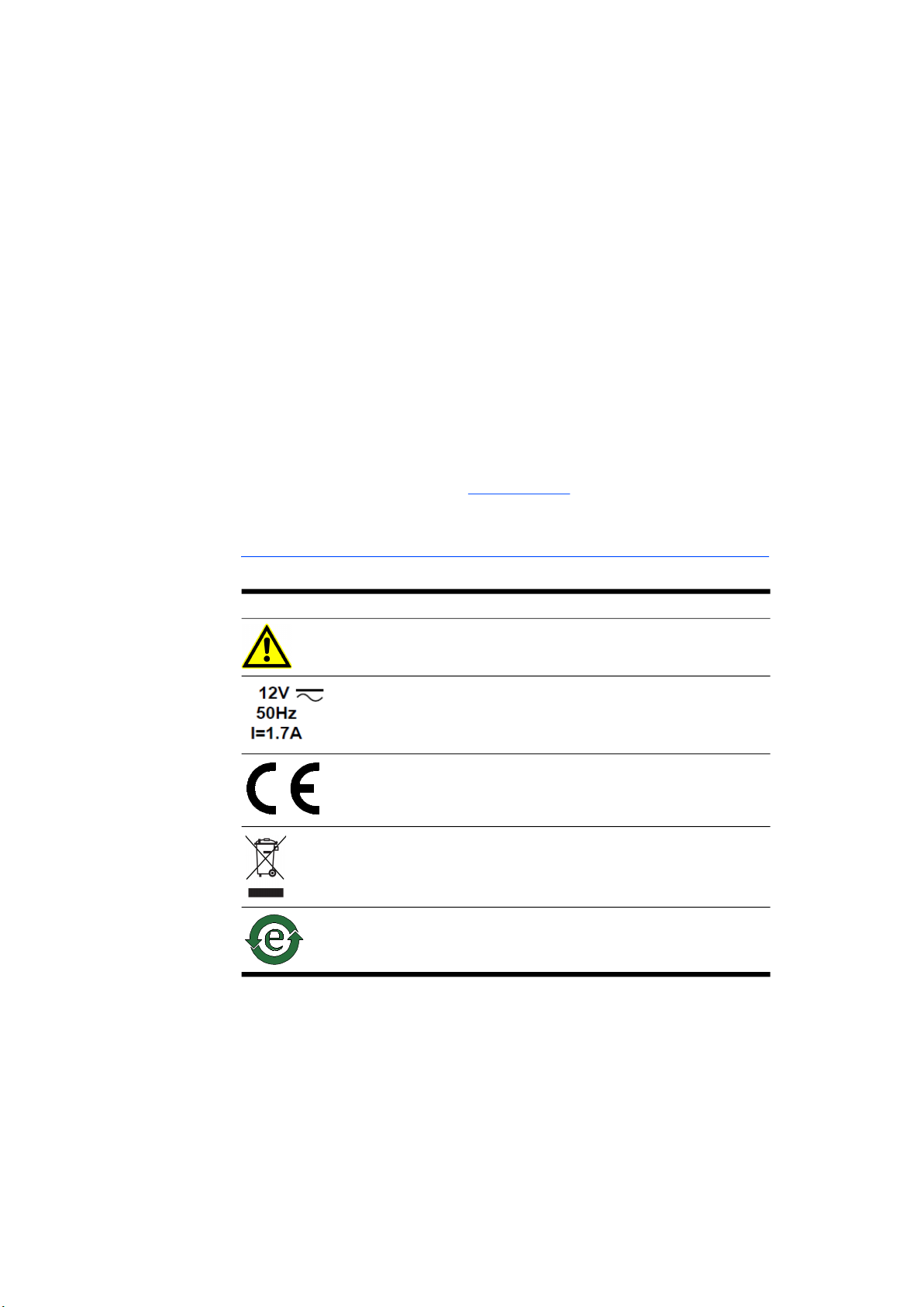
1.3 Identifications on the Product
The following symbols are used for identifying the product:
Please observe the information in the chapter “Technical Data” on page 25.
Symbol Description
The User's Guide must be read prior to the startup of the
product!
Operating voltage (rated voltage), current consumption
(max.), see chapter 4.3.1 on page 28
Marking for CE conformity, see chapter 1.5 on page 10
Marking for RoHS, see chapter 1.4.1 on page 10
Marking for China RoHS, see chapter 1.4.2 on page 10

ETAS General
CBS10x.1-2 - User’s Guide 10
1.4 RoHS Conformity
1.4.1 European Union
The EU Directive 2011/65/EU restricts the use of certain hazardous sub-
stances (RoHS conformity) for electrical and electronic devices.
ETAS confirms that the product meets this directive applicable in the European
Union.
1.4.2 China
With the China RoHS identification attached to the product or its packaging,
ETAS confirms that the product meets the guidelines of the "China RoHS"
(Management Methods for Controlling Pollution Caused by Electronic Informa-
tion Products Regulation) applicable in the People's Republic of China.
1.5 CE Marking
With the CE marking attached to the product or its packaging, ETAS confirms
that the product corresponds to the product-specific, applicable European
Directives. The CE Declaration of Conformity for the product is available upon
request.
1.6 Product Return and Recycling
The European Union (EU) released the Directive for Waste Electrical and Elec-
tronic Equipment - WEEE to ensure the setup of systems for collecting, treating
and recycling electronic waste in all countries of the EU.
This ensures that the devices are recycled in a resource-friendly way that does
not represent any risk to personal health and the environment.
Fig. 1-1WEEE Symbol
The WEEE symbol (see Fig. 1-1 on page 10) on the product or its packaging
identifies that the product may not be disposed of together with the remaining
trash.
The user is obligated to separately collect old devices and provide them to the
WEEE return system for recycling.
The WEEE Directive applies to all ETAS devices, but not to external cables or
batteries.
Additional information about the recycling program of ETAS GmbH is available
from the ETAS sales and service locations (see chapter 6 on page 37).
Dieses Handbuch passt für folgende Modelle
2
Inhaltsverzeichnis
Andere ETAS Zubehör Handbücher


