
FlowLine EchoSonic LU27 Series Bedienungsanleitung

Flowline, Inc. | 10500 Humbolt Street, Los Alamitos, CA 90720 p 562.598.3015 f 562.431.8507 w flowline.com QS300115 Rev C2
©2019 Flowline, Inc.
All Rights Reserved
Made in USA
EchoSonic®
Ultrasonic Liquid Level Transmitter
LU27 Series Quick Start

| 2 QS300115 Rev C2
WELCOME TO THE ECHOSONIC® QUICK START
The EchoSonic® quick start is meant to show some of the more common setup solutions to getting the
EchoSonic® up and running quickly. If you run into an issue that is not addressed here or wish to install
or set up with a non-standard configuration, please address the EchoSonic® Manual or refer to the
Flowline website at flowline.com.
WE DO YOUR LEVEL BEST
Thank you for purchasing Flowline’s EchoSonic®. This general purpose ultrasonic sensor provides non-contact
detection up to 9.8’ (3m) powered by the 4-20 mA loop. This quick start includes everything you’ll need to get
the sensor up and running. For complete information, please refer to EchoSonic® documentation located at
flowline.com.
COMPONENTS
Depending on how the sensor model that was shipped, you should have the EchoSonic® and Viton® gasket
which are required to install the EchoSonic®. Some models will have the USB® Key Fob (LI99-2001) included
with the EchoSonic®. Other will require the separate purchase of the Fob. A LI99-2001 Fob is required to
interface to WebCal® and configure the sensor.
.
EchoSonic®
LU27-00, LU27-01
LU27-10, LU27-11
Viton® gasket (1”)
P/N: 200128
USB® Key Fob
P/N: LI99-2001
QS300115 Rev C2 3 |
CONFIGURING THE ECHOSONIC®
Configuration of your sensor should be performed prior to mounting, since it requires connection to your PC.
Step 1: Install the WebCal® Software
Download WebCal® from www.flowline.com/webcal-software onto a PC with the following minimum
specifications:
Windows® XP/Vista/7/8/10, 10 MB storage space, 256 MB RAM, 1 USB 2.0 port
Double-click the WebCal® icon to install before proceeding to Step 2. You must have an active Internet
connection to install WebCal®, as it will automatically verify driver updates.
Step 2: Connect the USB Fob
NOTE: Do not connect the Fob until after you’ve installed WebCal®.
The sensor communicates to its configuration software through the USB Fob. Prior to connecting the Fob,
ensure that all external power is disconnected from the EchoSonic® as power is provided through the PC’s
USB 2.0 port. Do not use a cable connecting the sensor to the Fob any longer than 15 feet.
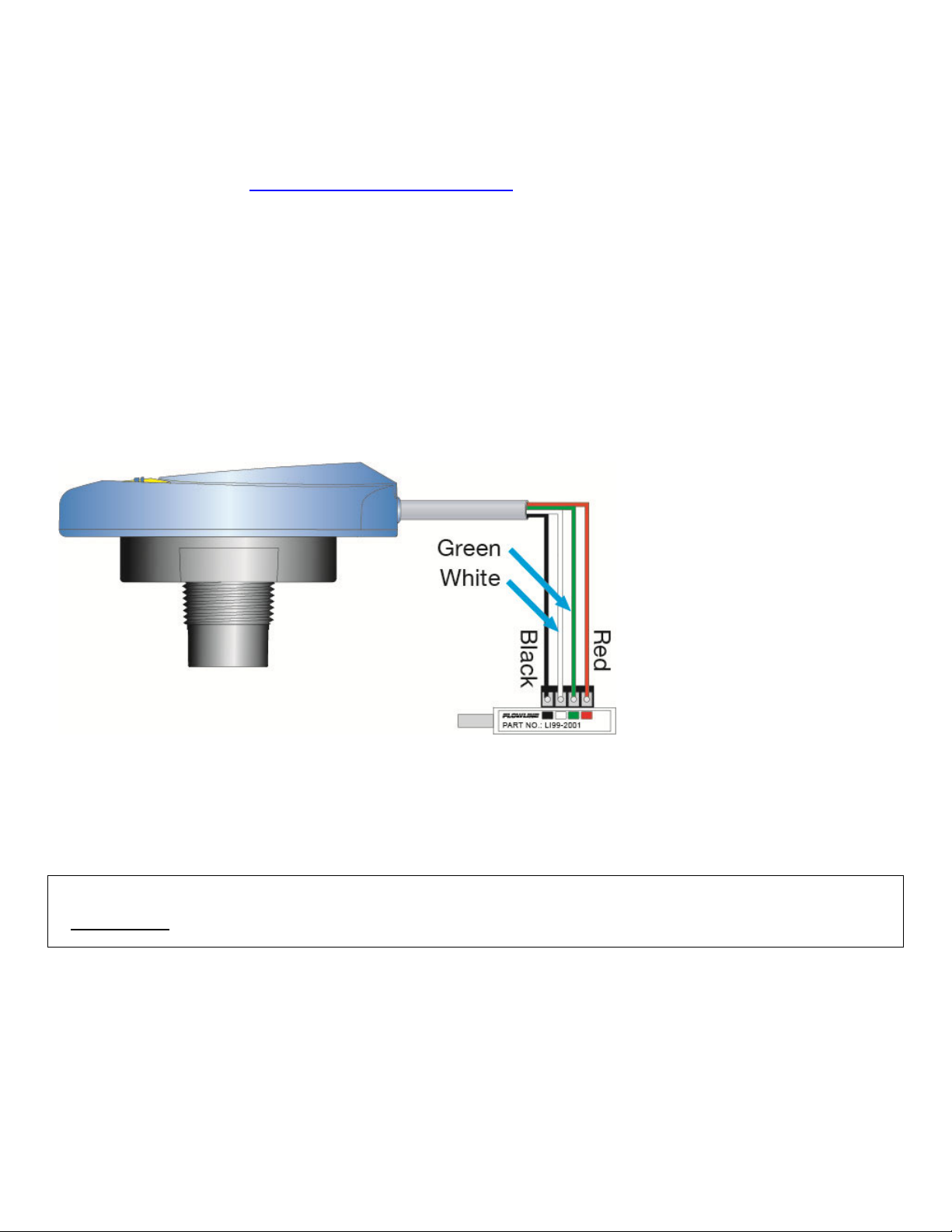
1) Connect the red, green, white, and black wires from the EchoSonic® to the corresponding colored terminals
on the Fob (as shown in the diagram).
2) Tighten the terminal screws with a slotted screwdriver.
3) Plug the Fob into your PC’s USB port.
NOTE: EchoSonic® II ships with the LI99-2001 Fob (white in color). The LI99-1001 Fob (black in color)
can be used with EchoSonic® II (LU27 series) to configure the sensor with WebCal®.

| 4 QS300115 Rev C2
Step 3: Configure through WebCal®
These instructions will walk you through configuration of the sensor through WebCal®. For more information,
click the WebCal® HELP button in the lower right corner or anywhere on the WebCal® screen or refer to the
EchoSonic® manual found at flowline.com.
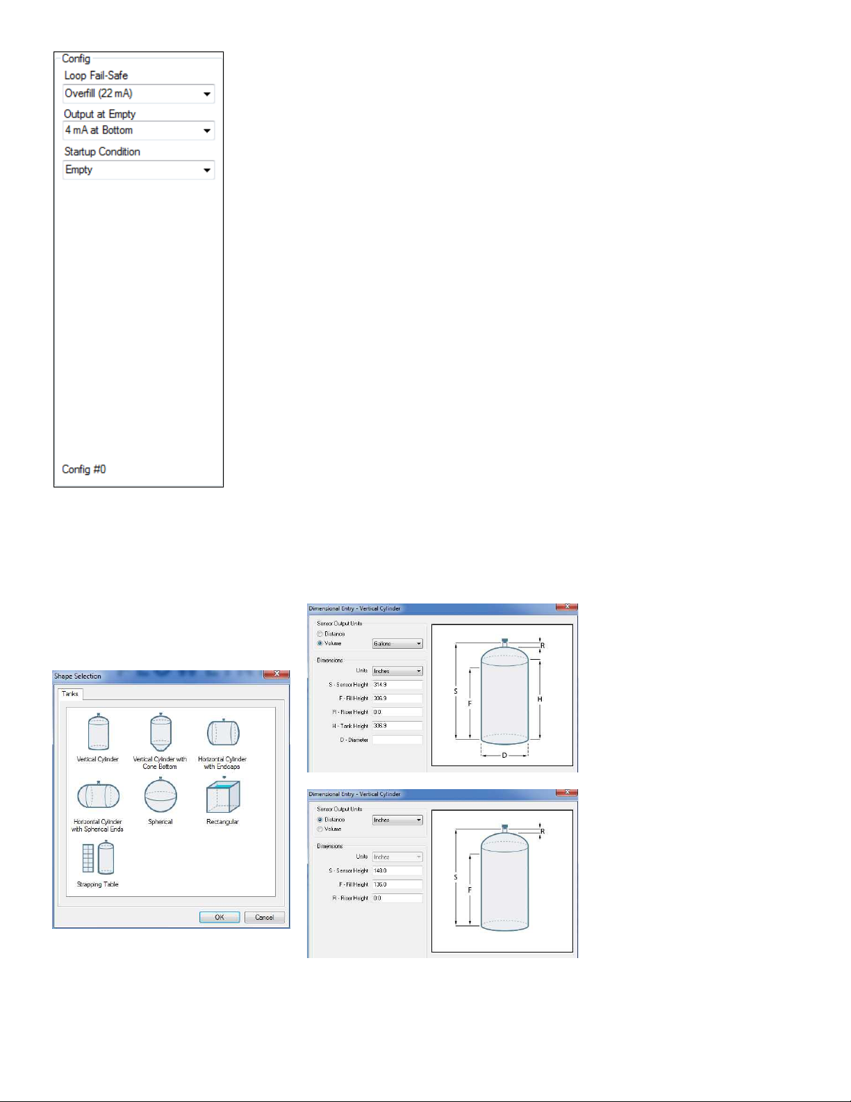
WebCal® Configuration Screen
QS300115 Rev C2 5 |
Using the drop-down menus on the left of the WebCal
®
screen set the
configuration for your application requirements. When a selection does not
apply to your application, “Not Applicable” will appear in the drop-down.
Make sure all drop-downs are set appropriately for your application before
moving to the Tank Level section.
Loop Fail Safe. Use this setting to choose the output level should the
sensor not receive an echo.
Output at Empty. Use this setting to change the 4-20 mA setting from
its default.
Startup Condition. During the 15-20 seconds during which the
EchoSonic® starts up, this describes the level at which it will begin
searching for the contents of the tank.
NOTE: If you would like to start over, click the Clear Screen button on the
right.
A New feature of WebCal® 6.0 is the ability to configure the sensor in volumetric units (Gallons or Liters) or in
the existing Distance (Height of Liquid) units (inches, cm, feet or meters). To change the actual units or to
change from Distance to Volume, press the Tanks button located near the center of the window.
Shape Selection Window
Dimensional Entry Window
This window will show the different
options for tank shapes available in
WebCal®.
Enter the dimensional
information for the tank.
You must enter all of the
fields shown.
Sensor Height:
Fill Height:
Riser Height:
Tank Height:
Diameter:
Note: Not all of the fields
apply for every tank
configuration.

| 6 QS300115 Rev C2
Enter the appropriate tank level set points for your application.
Units. Display measurements in inches or
centimeters.
Sensor Height. Distance measured from the
bottom of the empty tank to the bottom of the
transducer. Under factory configuration, this
becomes the 4 mA set point.
Fill Height. Distance measured from the bottom
of the empty tank to the maximum fill height
within the tank. Under factory configuration, this
becomes the 20 mA set point.
Tank Level Settings
The options on the right of the WebCal
®
screen to finalize the configuration.
Write to Unit. Send your configuration into EchoSonic®.
Wiring Diagram. Open PDF wiring schematic of your configuration.
Advanced. Configure advanced settings. Read the section below on
advanced setting options
Factory Config. Return EchoSonic® to the original factory configuration.
Clear Screen. Clears the screen of configuration settings.
Config File. Name, save, open or print your configuration for later use.
Finalize Settings

QS300115 Rev C2 7 |
The Advanced button is used for options available when setting up the sensor with special, non-standard
features. Many of these features are available for specific applications that may change from time to time.
Consult WebCal®'s HELP file for the latest information on the use of any of these features.
The more commonly used Advanced features are the
Invert Relay and Increase Output Filtering described
below.
Increase Output Filtering. Select this radio button
to add additional filtering to the 4-20 mA output.
Decrease Output Filtering. Select this radio button
to remove all output filtering on the 4-20 mA output.
Advanced Settings
Before configuration can be completed:
You must click the Write to Unit button to save the settings to the unit.
Then, click Wiring Diagram for a hard copy of the sensor’s settings.
Finally, enter the file name under which you wish to save the configuration file and click Save Config
File.
Configuration is now complete.
Disconnect the USB Fob before continuing to the next step: Mounting the EchoSonic®.
For updates to WebCal®, or to make sure you’re using the most up-to-date version available, click the Update
tab on the top of the WebCal® screen.

| 8 QS300115 Rev C2
MOUNTING THE ECHOSONIC®
The sensor should always be mounted perpendicular to the liquid surface using the provided Viton® mounting
gasket. Insure that there are no restrictions or obstacles in the path of the ultrasonic signal. Further mounting
information can be found on the Flowline website at flowline.com.
The EchoSonic® has a 1” NPT or G fitting and requires more care in mounting to reduce any coupling of the
ultrasonic signal to the mounting structure. The below listed fittings are recommended.
For installations in existing 2” fittings:
1) Use a LM52-1400 2” thread x 1” thread adapter (shown to the
right) or a LM52-1410 2” slip x 1” thread adapter. (An adapter
with an air gap around the 1 inch threads as shown is
recommended)
For installations in plastic tanks (use one of the following):
1) Use a 1” Bulkhead fitting, such as the LM52-1890 Bulkhead
fitting.
2) Use a larger Bulkhead fitting, such as the LM52-2890 in
combination with a reducer bushing such as the LM52-1400.
3) Weld a plastic 1” half coupling to the tank top.
For installations in metal tanks (use one of the following):
1) Use the recommended bulkhead fittings as shown above.
2) Use a flange with a 1” riser, such as the LM52-1850 (the
thread is above the plane of the flange). Do not use a blind
flange with a tapped 1” thread.
3) Use a larger flange with a 2” thread and add a reducer
bushing such as the LM52-1200.
Note: While installations directly into a 1”metal fitting are not
recommended, acceptable results may be obtained if the 1” fitting
is a half coupling in form and the outer diameter of the coupler is
tightly wrapped in vinyl tape to dampen vibrations.
For installations in open tanks and sumps:
1) Use Flowline's LM50-1001-1 side mount bracket.
Note: The Side Mount Bracket (LM50 series) is not designed for
use with stand pipes or as a method to secure stand pipes.
There are too few threads to properly hold the sensor and the
stand pipe.
LM52-1400
LM52-1410
LM52-2890
LM52-1850
LM50-1001

QS300115 Rev C2 9 |
Mounting with a Stand-Pipe:
A stand-pipe may be used to dampen turbulence, separate surface foam from the point of measurement or
increase performance in heavy vapor. When mounting the sensor in a stand-pipe, the minimum diameter of
the pipe is 2”. Larger diameter pipes can be used. The pipe should be attached with a coupling and reducer
bushing. The pipe length should run the measurement span and the bottom of the pipe should remain
submerged at all times to prevent foam from entering the pipe. Cut the bottom end of the pipe at 45° and drill
a 1/4”pressure equalization hole high in the dead band. The pumps should not drive liquid past the open end
of the standpipe which causes the liquid in the pipe to oscillate.
Stand-Pipe Mounting
IMPORTANT MOUNTING GUIDELINES
1) Never mount the sensor at an angle.
2) Liquid should never enter the dead band.
3) Mount at least 3” from the side wall.
4) Never mount the sensor in a vacuum.
5) Do not obstruct the sensor’s beam width.

| 10 QS300115 Rev C2
WIRING THE ECHOSONIC®
After mounting the sensor, make the necessary electrical connections. A wiring diagram with specific
recommendations for the sensor’s configuration can be printed from the WebCal® program. A typical wiring
diagram is shown on the next page.
Red (Power) and Black (Return) leads are for connection to a 24 VDC power supply or to a 4-20 mA loop
power source. The red and black wires can be extended more than 1000 feet using 22-gauge or larger wire,
however do not extend the green and white wires beyond 15’.
White (Tx) and Green (Rx) leads are reserved for use with WebCal® and should not be connected during
usage in the application. These wires should not be connected to WebCal® while power is supplied from any
source other than the LI99-2001 Fob.
NOTE: When using the White and Green wires with WebCal®, the maximum cable distance between the
EchoSonic® transmitter and the computer is 15’.
NOTE:Never allow the white or green wires to touch any power supply.
NOTE: EchoSonic® II ships with the LI99-2001 Fob (white in color). The LI99-1001 Fob (black in color)
can be used with EchoSonic® II (LU27 series) to configure the sensor with WebCal®.
Dieses Handbuch passt für folgende Modelle
6
Inhaltsverzeichnis
Andere FlowLine Zubehör Handbücher

FlowLine
FlowLine EchoPod DL34 Series Bedienungsanleitung

FlowLine
FlowLine EchoPro LR36 Series Bedienungsanleitung

FlowLine
FlowLine EchoPod DL24 Series Bedienungsanleitung

FlowLine
FlowLine EchoSonic II Bedienungsanleitung

FlowLine
FlowLine EchoPro LR36 Series Bedienungsanleitung

FlowLine
FlowLine EchoWave LG10 Series Bedienungsanleitung

FlowLine
FlowLine EchoSwitch LU74 Series Bedienungsanleitung

FlowLine
FlowLine EchoPod DL10 Series Bedienungsanleitung

FlowLine
FlowLine EchoSonic II LU27 Series Bedienungsanleitung

FlowLine
FlowLine EchoPod DX10 Series Bedienungsanleitung


