JUMO LOGOPRINT 500 Bedienungsanleitung

Printing Recorder
with text printing and
LED dot-matrix display
B 70.6030.0
Operating Manual
2009-06-03/00353037

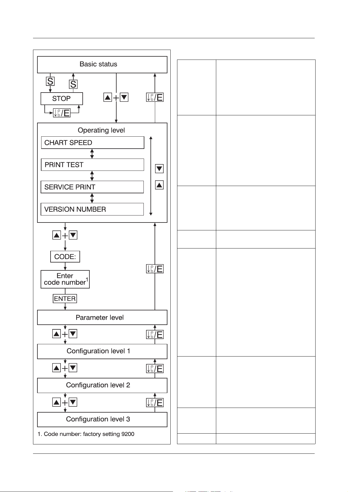
Key functions
e- Paper (chart) fast-forward,
when recording is stopped
(in basic status)
- Abort parameter
entry (Exit)
- Leave the levels
S-Start/Stop
of recording
- Selection of decimal point
position when entering values
- For text entry:
Fast character selection
(jump to “ ”, “0”, “A”, “a”, “°”,
“2”, “À”, “à”)
F-Function key for special
functions
(press for at least 4sec)
factory setting:
print the scaling
l, r- Shift cursor left/right
(selecting position)
h, R- Select display:
- Instrument designation,
date & time
- Measurements of the
channels
- System status
- Parameter selection
- Channel selection
- Value selection
from a table of values
- Increment/decrement
present digit
E- Initiate parameter entry
-Confirmentry
- Acknowledge error message
- Activate/de-activate statistical
display (in basic status)
l+ r- Activate/de-activate the
display of status/error
messages
h+ R- Change to next level

Contents
1 Introduction 7
1.1 Preface ......................................................................................................... 7
1.2 Arrangement of the documentation .......................................................... 8
1.2.1 Structure of this operating manual ............................................................... 8
1.3 Typographical conventions ........................................................................ 9
1.3.1 Warning signs ............................................................................................... 9
1.3.2 Note signs ..................................................................................................... 9
1.3.3 Presentation ............................................................................................... 10
2 Instrument description 11
2.1 Display and controls ................................................................................ 11
2.2 Basics of operation ................................................................................... 12
3 Operation and visualisation 23
3.1 Limit monitoring by limit comparators ................................................... 23
3.2 Open-collector outputs ............................................................................ 25
3.3 Different chart speeds (paper feed) ........................................................ 26
3.4 Graphic print-out ...................................................................................... 27
3.4.1 Measurement traces (signal traces) ............................................................ 29
3.4.2 Event traces ................................................................................................ 30
3.5 Text printing ............................................................................................... 31
3.5.1 Printing priorities ......................................................................................... 31
3.5.2 Printing modes ........................................................................................... 34
3.5.3 Queuing during text printing ....................................................................... 35
3.5.4 Limit comparator texts, external text, binary-linked external text .............. 36
3.5.5 Report ......................................................................................................... 38
3.5.6 Switching the chart speed .......................................................................... 41
3.5.7 “Power On” and “Power Off” texts ............................................................. 42
3.5.8 Scaling ........................................................................................................ 43
3.5.9 Time ............................................................................................................ 46
3.5.10 Print out channel numbers ......................................................................... 47
3.5.11 Recording start and stop ............................................................................ 47
3.5.12 Incrementing the two event counters ......................................................... 48
3.5.13 Print test ..................................................................................................... 49
3.5.14 Service print ................................................................................................ 50

Contents
3.6 Colour assignment ................................................................................... 51
3.7 Relationship between measurement range and scaling ....................... 52
4 Configuration table 53
4.1 Operating examples ................................................................................. 53
4.2 Table of the configuration parameters ................................................... 55
4.2.1 Operating level (S-level) .............................................................................. 55
4.2.2 Parameter level (P-Level) ............................................................................ 56
4.2.3 Configuration level 1 (C1-level) ................................................................... 57
4.2.4 Configuration level 2 (C2-level) ................................................................... 63
4.2.5 Configuration level 3 (C3-level) ................................................................... 66
5 Identifying the instrument version 69
5.1 Instrument description ............................................................................. 69
5.2 Order details .............................................................................................. 70
6 Installation 71
6.1 Site and climatic conditions .................................................................... 71
6.2 Assembly in a control panel ..................................................................... 71
7 Electrical connection 73
7.1 Installation notes ...................................................................................... 73
7.2 Technical data ........................................................................................... 74
7.3 Connection diagram ................................................................................. 78
7.4 Electrical isolation .................................................................................... 81
8 Starting up 83
8.1 Opening and closing the door ................................................................. 83
8.2 Marking the channel label ........................................................................ 83
8.3 Fitting the print head ................................................................................ 84
9 Consumables 85
9.1 Consumables ............................................................................................ 85

Contents
9.2 Removing and replacing the chart cassette .......................................... 86
9.2.1 Changing the roll chart ............................................................................... 88
9.2.2 Changing the fanfold chart ......................................................................... 89
10 Extra codes and accessories 91
10.1 Converting the chart cassette ................................................................. 91
10.2 “8 logic inputs”, “interface for ER8”,
“voltage output” ........................................................................................ 92
10.3 External relay module ER8 ....................................................................... 93
10.4 Setup program .......................................................................................... 95
10.5 Mathematics and logic module ............................................................... 97
10.6 Interface (RS422/RS485) .......................................................................... 98
11 Fault-finding 99
11.1 What to do if … ......................................................................................... 99
12 Appendix 101
12.1 Error messages ....................................................................................... 101
12.2 Hardware fault ......................................................................................... 103
12.3 Status messages .................................................................................... 104
12.4 Character set .......................................................................................... 105
12.5 Summary of the parameters .................................................................. 106
13 Index 109

Contents

7
1 Introduction
1.1 Preface
Please read this Operating Manual before commissioning the instrument.
Keep the operating manual in a place which is accessible to all users at all
times.
Please assist us to improve this manual, where necessary.
Your suggestions will be appreciated.
Phone in Germany (0661) 6003-727
from abroad (+49) 661 6003-0
Fax in Germany (0661) 6003-508
from abroad (+49) 661 6003-607
H
All the necessary settings are described in this manual. However, if
any problems should arise during start-up, you are asked not to
carry out any unauthorised manipulations. You could endanger
your rights under the warranty!
Please contact the nearest JUMO office or the head office.
E
When returning modules, assemblies or components, the
regulations of EN 61340-5-1 and EN 61340-5-2 “Protection of
electronic devices from electrostatic phenomena” must be
observed. Use only the appropriate ESD packaging for transport.
Please note that we cannot accept any liability for damage caused
by ESD.
ESD=electrostatic discharge
B

1 Introduction
8
1.2 Arrangement of the documentation
The documentation for this instrument consists of the following parts:
Operating
Manual
B 70.6030.0
This operating manual is always supplied with the instrument. It is addressed
to OEMs (original equipment manufacturers) and users with the appropriate
technical know-how.
In addition to installation and electrical connections, it also includes
information on commissioning, operation, and setting the parameters in the
instrument, on extra codes and accessories.
Interface
Description
B 70.6030.2
This manual is supplied with the instrument if the Extra Code “RS422” or
“RS485” was ordered. It provides information about communication with
higher-level (supervisory) systems.
Setup
Program
B 70.6030.3
This manual describes the installation of the setup program, and also deals
with special features in the operation of the setup program.
Online Help The online help is part of the setup program. It is a Windows1online help.
1.2.1 Structure of this operating manual
This operating manual is laid out so that the user is immediately able to get on
with operating and configuring the instrument. To this end, the chapters which
describe procedures which are usually only carried out once, such as
description of the instrument, type designations, assembly and electrical
connections, are placed at the end of the manual.
1. Microsoft and Windows are registered trademarks
of the Microsoft Corporation

9
1 Introduction
1.3 Typographical conventions
1.3.1 Warning signs
The signs for Danger and Warning are used in this manual under the
following conditions:
V
Danger
This symbol is used where there may be danger to personnel if the
instructions are disregarded or not followed accurately!
A
Warning
This symbol is used where there may be danger to equipment or data if the
instructions are disregarded or not followed accurately!
E
Warning
This symbol is used where special care is required when handling
components which are liable to damage from electrostatic discharge.
1.3.2 Note signs
H
Note
This symbol is used when your attention is drawn to a special remark.
v
Reference
This sign refers to further information in other manuals, chapters or sections.
abc1Footnote
Footnotes are notes which refer to certain points in the text. Footnotes
consist of two parts:
Marking in the text and the footnote text.
The markings in the text are arranged as continuous superscript numbers.
h
Action
This symbol shows that an action to be performed is described.
The individual steps are designated by the star, for example:
hPress the hkey
hConfirm with E

1 Introduction
10
1.3.3 Presentation
h+ E
Keys
Keys are shown in a box. Both symbols and texts are possible. If a key has
multiple functions, then the text shown is that which corresponds to the
currently active function.
Program
Manager
Screen texts
Texts which are displayed in the setup program are distinguished by italic
script.
Edit Î
instrument data
Menu items
The menu items in the setup program which are referred to in this manual are
shown in italic script. Menu name, menu item, and sub-menu item are
separated from one another by “Δ.
Inhaltsverzeichnis