Magnum MCC-35ASP Technisches Datenblatt

Product instruction manual
Magnum MCC-35ASP
The Magnum has been designed to be user friendly,
however we strongly recommend you take a few minutes
to read through this manual to ensure correct operation.
Keep this manual safe for future reference.

MCC-35AS 2
INDEX
Chapter 1 Introduction ..................................................................................... 1
1.1Preface ................................................................................................ 1
1.2 Specification ....................................................................................... 1
Chapter 2 Safety .............................................................................................. 3
2.1Environment ......................................................................................... 4
2.2 Do’s and Don’ts .................................................................................. 4
2.3 Cautions .............................................................................................. 5
Chapter 3 Main Parts and Assies ..................................................................... 6
3.1Main Parts ............................................................................................ 6
3.2 Infeed Part .......................................................................................... 7
3.3 SC Unit Part ........................................................................................ 8
3.4 Crease Unit Part ................................................................................. 9
Chapter 4 Installation ..................................................................................... 10
4.1 Touch Screen Installation .................................................................. 10
4.2 Outfeed Tray Installation ................................................................... 10
4.3 Deflectors and Side Guide Placement .............................................. 11
4.5 Power Socket and Switch ................................................................. 11
Chapter 5 Operation ...................................................................................... 12
5.1 Welcome Screen .............................................................................. 12
5.2 Touch Screen Calibration. ................................................................. 13
5.3 Main Screen ...................................................................................... 14
5.4 Main Running Screen ....................................................................... 15
5.5 Manual Programming Screen ........................................................... 16
5.5.1 Main Icon Introduction ............................................................ 16
5.5.2 Manual Input ........................................................................... 17
5.5.2.1 Paper Size Setting ........................................................ 17
5.5.2.2 Slit Setting .................................................................... 19
5.5.2.3 Cut Setting .................................................................... 20
5.5.2.4 Crease Setting .............................................................. 21
5.5.2.5 Partial Perforating Setting ............................................. 22
5.6 Quick Programming Screen .............................................................. 24
5.6.1 Introduction of Sheet Data: ..................................................... 24
5.6.2 Create a Template by Quick Programming ............................. 25
5.6.2.1 Set Paper Size .............................................................. 25
5.6.2.2 Set Card Size ............................................................... 26
5.6.2.3 Set Trim and Gutter ...................................................... 26
5.6.2.4 Set Crease for Each Finished Piece ............................. 27
5.6.2.5 Set Partial Perforating Data for Each Finished Piece ... 27
5.6.2.6 Preview for the Template .............................................. 28
5.7 Save or Recall a Template ................................................................ 29
5.7.1 Save a Template ..................................................................... 29
5.7.2 Recall a Template ................................................................... 29

MCC-35AS 3
5.8 System Setting .................................................................................. 30
5.9 Feature Function ............................................................................... 31
5.9.1 Register Mark ......................................................................... 31
5.9.1.1 How to Create a Register Mark .................................... 31
5.9.1.2 How to Use Register Mark ............................................ 31
5.9.2 “+” Dual Function .................................................................... 33
Chapter 6 Options .......................................................................................... 35
6.1 Option Tools ..................................................................................... 35
6.1.1 Slide-in Tools .......................................................................... 35
6.1.2 Linear Tools ............................................................................ 35
6.1.3 Strike Perforator ..................................................................... 36
6.2 Option Function- Barcode Reader .................................................... 36
6.2.1 Why need barcode reader? .................................................... 36
6.2.2 What is barcode? .................................................................... 37
6.2.2.1 Code 39 ........................................................................ 37
6.2.2.2 Definition of a complete Magnum barcode. ..................... 37
6.2.3 How to create barcodes? ........................................................ 38
6.2.4 Where should the barcode print on the layout? ...................... 41
6.2.5 How the barcode work? .......................................................... 41
Chapter 7 Trouble Shooting ........................................................................... 43
7.1 Show warning C-4, C-6,C-7,C-8 ....................................................... 43
7.2 Show warning C-12 .......................................................................... 45
7.3 Show warning C-9 ............................................................................ 46
7.4 Show warning C-10 .......................................................................... 47
7.5 Don’t show warning C-2 when tray empty......................................... 48
7.6 Show warning C-5 ............................................................................ 49
7.7 Show warning C-11 ........................................................................... 49
7.8 Show Error E-3 ................................................................................. 50
7.9 Show Error E-2 ................................................................................. 50
7.10 Images Shrink/Stretch or Shift Caused by Printing ......................... 53
Chapter 8 Maintenance .................................................................................. 55

MCC-35AS 1
Chapter 1 Introduction
1.1Preface
This manual only applies to MCC-35AS Multi Card machine.
Before using the machine, please read the instruction manual carefully.
Please keep the manual safe so that you are able to consult to it at any time.
Any question while operating please contact our technicians.
1.2 Specification
Item Parameter
Dimensions Length*Width*Height (mm) 1960X7001200
Power Source AC110V-240V,50/60Hz
Power 800W
Weight 150kg
Infeed Paper Spec
Max(W*L) 330mm×650mm
Min(W*l) 210mm×210mm
Gram Weight 150g-350g/0.15-0.35mm
Output Size Max(W*L) 330mm×650mm
Min(W*l) 50mm×48mm
Cross Cutter
First Cut 3.2-15mm
Last Cut 5-15mm
Gutter Cut 3-15mm
Min Card Size for Cutter 48mm
Max Qty for Cutter per Sheet 32
Accuracy for Cutting ±0.2-0.4mm
Slit
Slitters 6
Side Trim 3.2-38mm
Gutter Slit 0 or 5-15mm
Accuracy for Slitting ±0.3mm
Crease
Max Qty for Crease per Sheet 32
Crease Depth Adjustment 8 Level Auto Adjust
Crease Direction Both
Crease Die Spec. 1.0mm
Accuracy for Creasing ±0.3mm
Scoring Tools Option
Perforator.
Cross Perforator Die Option 12/24TPI
Rotary Perforator Assembly Option 12/24TPI
Max Qty for Rotary Perf. Assembly 8 sets
Strike Perf. Assembly and Max Qty Option 12TPI,8 sets
Feeding Type Top Vacuum

MCC-35AS 2
Speed A4 trimming 4 sides, crease in middle 20Sheets/min
Pile Loading 100mm
Double Feed Detect Ultrasonic Detecting
Skew Adjustment Manually Adjustment
Image Compensation X/Y Direction Compensation
User Template Storage 64
Note: The machine is keep upgrading, specification and information in this
manual is updated as per the change without notice.

MCC-35AS 3
Chapter 2 Safety
Please shut down the machine before the maintenance.
In order to avoid any mistake when re-connecting wires back, we advise you
to mark each connector before replace of any electrical component.
Mind that every connection should be firm, first hold both sides of the
connector, and then, in the middle, not firm connection is possible to damage
the electrical components.
Power supply
AC input,Voltage/Frequency is:
AC 110-240V/50-60Hz.
!
If the voltage or frequency are not in the range, the
machine may not be used normally or even may
cause unrecoverable damage
Power cord,Over 10A current is endurable
!
1. Do not remove the cord when the machine is running,
illegal operation may cause component damage or
machinery jam
2. Remove the cord when you are installing components.
Ground symbol. If you see this symbol in any place,
please do not touch it anyhow, or uninstall it.
!
If the ground is not well connected, it may cause human
body injury.

MCC-35AS 4
2.1Environment
Temperature:10°Cto35°C
Humidity:30%to70%
Altitude:Belowelevation1000m
Thereisnocorrosivenessgas,flammablegas,oilmistandsooninroom
2.2 Do’s and Don’ts
Do-Read this manual and fully understand before the operation.
Do-Check the plug and machine voltage and frequency to your main
supply, and that the socket has a correct working earth lead for this single
insulated machine
Do use at least a 10 amp power source at 220 V. (20Amp/100V).
Do make sure all safety covers are in place. The top covers have an
interlock switch which will disable the unit if removed
Do open or close the cover slowly
Do contact the local maintenance center before you are about to move
the machine.
Do disconnect the power before clean the inner side.
Do unplug the cord if you won’t use the machine for a long while,
Do be careful of the blade edge
Don’t install the machine on an unstable ground.
Don’t operating with wet hand, especially plug or unplug the cord.
Don’t wear long hair, loose fitting clothes or put your fingers into the
creasing unit nip, while the operation..
Don’tplaceanyreceptacleswithanyliquidonanysurfaceofmachine.

MCC-35AS 5
Don’t‐put other pieces, especially tiny pieces on loading table.
Don’t-alter or uninstall the machine, unless by Magnum
authorized engineer.
Don’t touch any running parts while running
Don’t shut down the machine while running.
Don’t put heavy matter on machine or shock it.
Don’t put the side guide under the feeding system.
2.3 Cautions
Be careful of any metal or flammable thing in internal machine, or it may cause
fire or electronic shock. If it happens, first shut down the power, disconnect the
cord, and then contact the technician.
If machine becomes heat, smoke, or smelly, shutdown at once, disconnecting
the cord, and contact the maintenance staff.
MCC-35AS 6
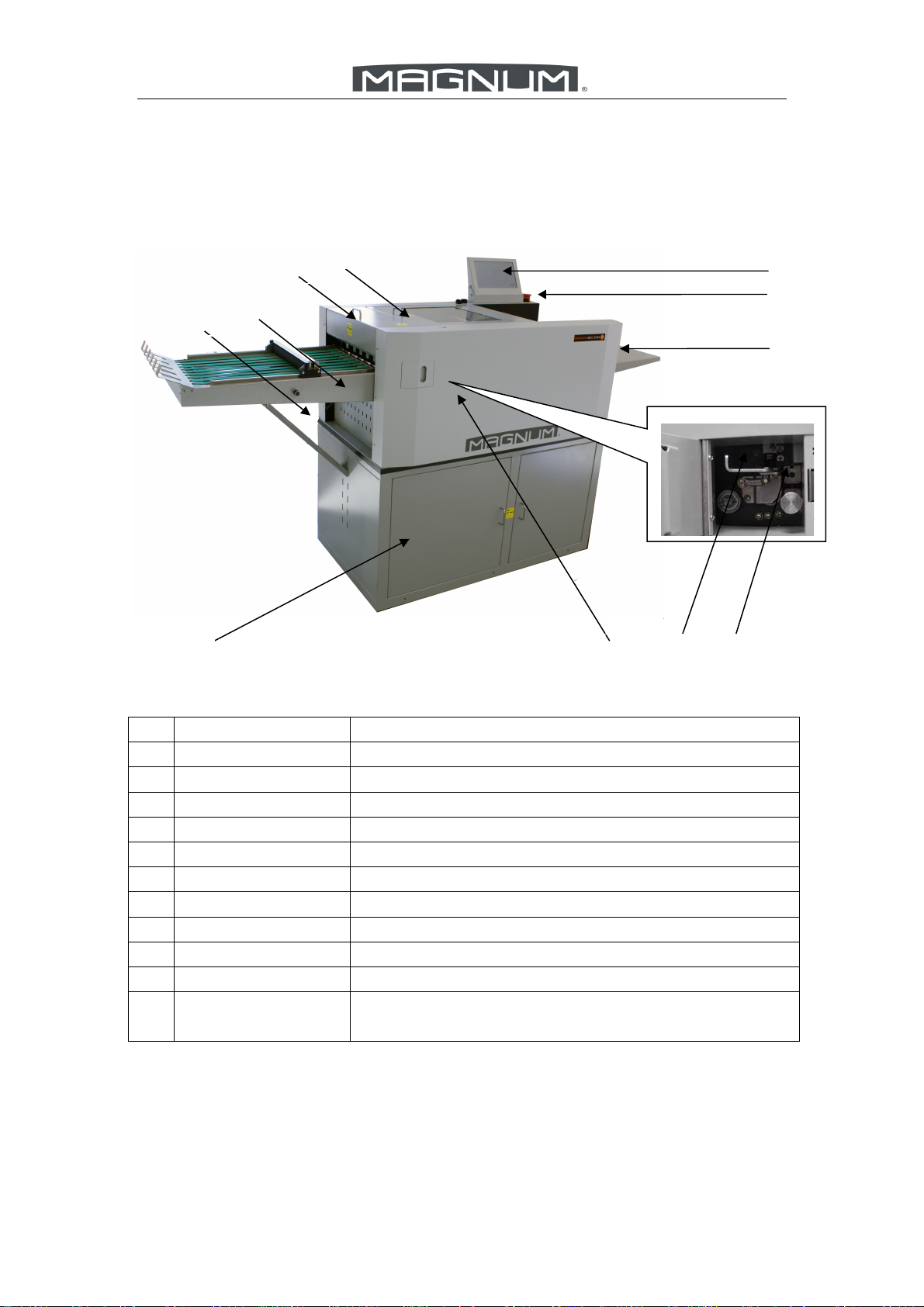
Chapter 3 Main Parts and Assies
3.1Main Parts
No. Description Remark
1 SC unit Slit and cut according to the template
2 Crease Unit Make Creasing,Perforating,or Partial Perforating
3 Card Collector Collect finished business card
4 Outfeed Tray Collecting finished Bigger Cards or Sheets
5 Stand Place Waste Box and Store Room for parts or sheets
6 Crease Side Cover Exchange the crease die or perforating die
7 Lock device Protect Crease Die from sliding out
8 Crease Die Creasing or change perforator for perforating
9 Loading Table Loading Paper
10 Emergency Button Shut down machine while emergency.
11 Color Touch
Screen
Control panel and display
11
8 7 65
1
2
3
4
10
9

MCC-35AS 7
3.2 Infeed Part
No. Description Remark
1 Switch Main power switch
2 Releasing Button Release Elevator while Elevator Error
3 Side Guide Post Regular the infeed paper
4 Paper Deflectors Avoid paper floating too much
5 Air Blast Knob Adjust the air blast
6 Paper Separator
Knob
Adjust the height of separator to change the gap
between separator and vacuum belt, according to
different paper thickness
7 Height Knob Adjust the table height going up
8 Skew Wheel Adjust the infeed skew
9 Loading Extension
Table
For Loading longer Paper
10 Movable Side Guide Back Stop or regular the infeed paper.
6
5
10
1 2
3
4
7
8
9
Inhaltsverzeichnis
Andere Magnum Bindemaschine Handbücher

Magnum
Magnum iBind A20 Bedienungsanleitung

Magnum
Magnum MCR-35 Technisches Datenblatt

Magnum
Magnum MC-35A Technisches Datenblatt

Magnum
Magnum MCR-46 Betriebshandbuch

Magnum
Magnum MEC21 Technisches Datenblatt

Magnum
Magnum MC-35M Technisches Datenblatt

Magnum
Magnum MCC-35 Technisches Datenblatt

Magnum
Magnum MCPF-35 Technisches Datenblatt

Magnum
Magnum MEC46 Technisches Datenblatt


