PKP DM04 Bedienungsanleitung

Instruction Manual
DM04
Magnetic inductive flowmeter
PKP Prozessmesstechnik GmbH
Borsigstraße 24
D-65205 Wiesbaden- ordenstadt
Tel.: ++49-(0)6122-7055-0
Fax: ++49-(0)6122-7055-50
Email: [email protected]

Instruction Manual DM04
Table of contents page
0 About this operating manual.......................................................................................................................2
1 Device description......................................................................................................................................3
1.1 Deliver , unpacking and accessories.......................................................................................................3
1.2 Intended use.............................................................................................................................................4
1.3 Exclusion of liabilit ................................................................................................................................4
2 Safet instructions.......................................................................................................................................5
3 Construction and function...........................................................................................................................6
4 Installation of DM04...................................................................................................................................7
4.1 Installation instructions............................................................................................................................7
4.2 Mounting..................................................................................................................................................8
5 Electrical connection...................................................................................................................................9
5.1 Wirings...................................................................................................................................................10
6 Commissioning and measuring mode.......................................................................................................11
6.1 Commissioning......................................................................................................................................11
6.2 Switching on and off..............................................................................................................................11
6.3 Measuring mode.....................................................................................................................................11
7 Maintenance and cleaning.........................................................................................................................13
7.1 Return shipment to the manufacturer.....................................................................................................13
8 Disassembl and disposal.........................................................................................................................14
9 Technical data............................................................................................................................................15
9.1 Characteristics DM04............................................................................................................................15
9.2 Materials table........................................................................................................................................16
9.3 Pressure drop..........................................................................................................................................16
9.4 Temperature limits.................................................................................................................................17
9.5 Dimensions............................................................................................................................................18

Instruction Manual DM04
0 About this operating manual
The operating manual is aimed at specialists and semi-skilled personnel.
Before each step, read through the relevant advice carefull and keep to the specified order.
Thoroughl read and understand the information in the section “Safet instructions".
If ou have an problems or questions, please contact our supplier or contact us directl at:
PKP Prozessmesstechnik GmbH
Borsigstraße 24
D-65205 Wiesbaden- ordenstadt
Tel: +49 (0) 6122-7055-0
Fax: +49 (0) 6122-7055-50
Hazard signs and other symbols used:
WARNING! / CAUTION! Risk of injur !
This sign indicates dangers that cause personal injuries that can lead to health defects or cause consid-
erable damage to propert .
CAUTION! Electric current!
This sign indicates dangers which could arise from handling of electric current.
CAUTION! Material damage!
This sign indicates actions which could lead to possible damage to material or environmental damage.
ADHERE TO OPERATING MANUAL! NOTICE!
This s mbol indicates important notices, tips
or information.
NO DOMESTIC WASTE!
The device must not be disposed of together
with domestic waste.
Pa attention to and compl with information
that is marked with this s mbol.
Follow the specified instructions and steps.
Adhere to the given order.
Check the specified points or notices.
Reference to another section, document or
source.
• Item.
- 2 - PKP Prozessmesstechnik • 08/2019

Instruction Manual DM04
1 Device description
The devices of the DM04 series from PKP, is a non-contact flow sensor. The measurement is performed us-
ing magnetic induction and works without an moving parts.
The DM04 is used for measuring or metering water and aqueous solutions. The compact design and inde-
pendence from the intake and discharge sections allows the DM04 to be used under a variet of conditions.
Versions:
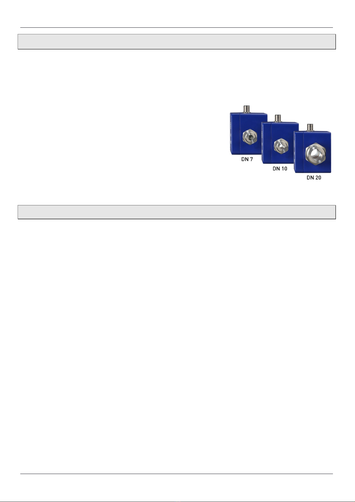
The DM04 is available in nominal sizes DN 7, DN 10 and DN 20.
The versions can be configured differentl .
Type plate:
The t pe plate sticker is located at the bottom side of the DM04.
It contains the most important data, the connection diagram and the ar-
row for the flow direction.
1.1 Delivery, unpacking and accessories
All units have been carefull checked for their operational reliabilit before shipment.
Immediatel after receipt, please check the outer packaging for damages or an signs of improper hand-
ling.
Report an possible damages to the forwarder and our responsible sales representative. In such a
case, state a description of the defect, the t pe and the serial number of the device.
Report an in-transit damage immediatel . Damage reported at a later date shall not be recognized.
Unpacking:
Carefull unpack the unit to prevent an damage.
Check the completeness of the deliver based on the deliver note.
Scope of delivery:
1x DM04 as ordered.
1x Operating manual.
1x Packaging.
- 3 - PKP Prozessmesstechnik • 08/2019

Instruction Manual DM04
IMPORTANT!
Use the t pe plate to check if the delivered unit corresponds to our order.
In particular, for devices with electrical components, check to see if the correct power sup-
pl voltage is specified.
Accessories:
Connection cable with moulded M12x1 coupling socket.
M12x1 coupling socket as component.
1.2 Intended use
The magnetic inductive flow sensor DM04 must onl be used for measuring and metering liquids with a
minimum conductivit of 50 μS/cm.
WA NING! No safety component!
The magnetic inductive flow sensor of the series DM04 is not safet components in accordance with
Directive 2006-42-EC (Machine Directive).
Never use the DM04 as a safet component.
The operational safet of the device supplied is onl guaranteed b intended use. The specified limits
(§ 9 “Technical data”) ma under no circumstances be exceeded.
Before installing the device, check that the wetted materials of the device are compatible with the media be-
ing used (§ 9.2 “Materials table”).
Measuring tube empt (or partiall filled). / Conductivit too low.
The green LED ma blink irregularl if the measuring tube of the DM04 is empt or partiall filled
or if the conductivit of the fluid being used is too low. Random pulses will be present at the output,
but the do not represent an actual flow.
Ensure that the measuring tube of the DM04 is alwa s completel filled (§ 4.1 "Installation
instructions").
Ensure that the conductivit of the fluid is at least 50 μS/cm.
1.3 E clusion of liability
We accept no liabilit for an damage or malfunctions resulting from incorrect installation, in-appropriate
use of the device or failure to follow the instructions in this operating manual.
- 4 - PKP Prozessmesstechnik • 08/2019

Instruction Manual DM04
2 Safety instructions
Before ou install the DM04, read through this operating manual carefull . If the instructions contained within it
are not followed, in particular the safet guidelines, this could result in danger for people, the environment, and
the device and the s stem it is connected to.
The DM04 correspond to the state-of-the-art technolog . This concerns the accurac , the operating
mode and the safe operation of the device.
In order to guarantee that the device operates safel , the operator must act competentl and be con-
scious of safet issues.
PKP provides support for the use of its products either personall or via relevant literature. The customer
verifies that our product is fit for purpose based on our technical information. The customer performs cus-
tomer- and application-specific tests to ensure that the product is suitable for the intended use. With this veri-
fication all hazards and risks are transferred to our customers; our warrant is not valid.
Qualified personnel:
The personnel who are charged for the installation, operation and maintenance of the DM04 must hold a
relevant qualification. This can be based on training or relevant tuition.
The personnel must be aware of this operating manual and have access to it at all times.
The electrical connection should onl be carried out b a full qualified electrician.
General safety instructions:
In all work, the existing national regulations for accident prevention and safet in the workplace must be
complied with. An internal regulations of the operator must also be complied with, even if these are not
mentioned in this manual.
Degree of protection according to EN 60529:
Please ensure that the ambient conditions at the site of use does not exceed the requirements for the
stated protection rating (§ 9 “Technical data”).
Prevent freezing of the medium in the device with appropriate measures.
Onl use the DM04 if it is in perfect condition. Damaged or fault devices must be checked without
dela and, if necessar , replaced.
When fitting, connecting and removing the DM04 use onl suitable appropriate tools.
Do not remove or obliterate t pe plates or other markings on the device, as otherwise the warrant is
rendered null and void.
Special safety instructions:
Warnings that are specificall relevant to individual operating procedures or activities can be found at the be-
ginning of the relevant sections of this operating manual.
- 5 - PKP Prozessmesstechnik • 08/2019

Instruction Manual DM04
3 Construction and function
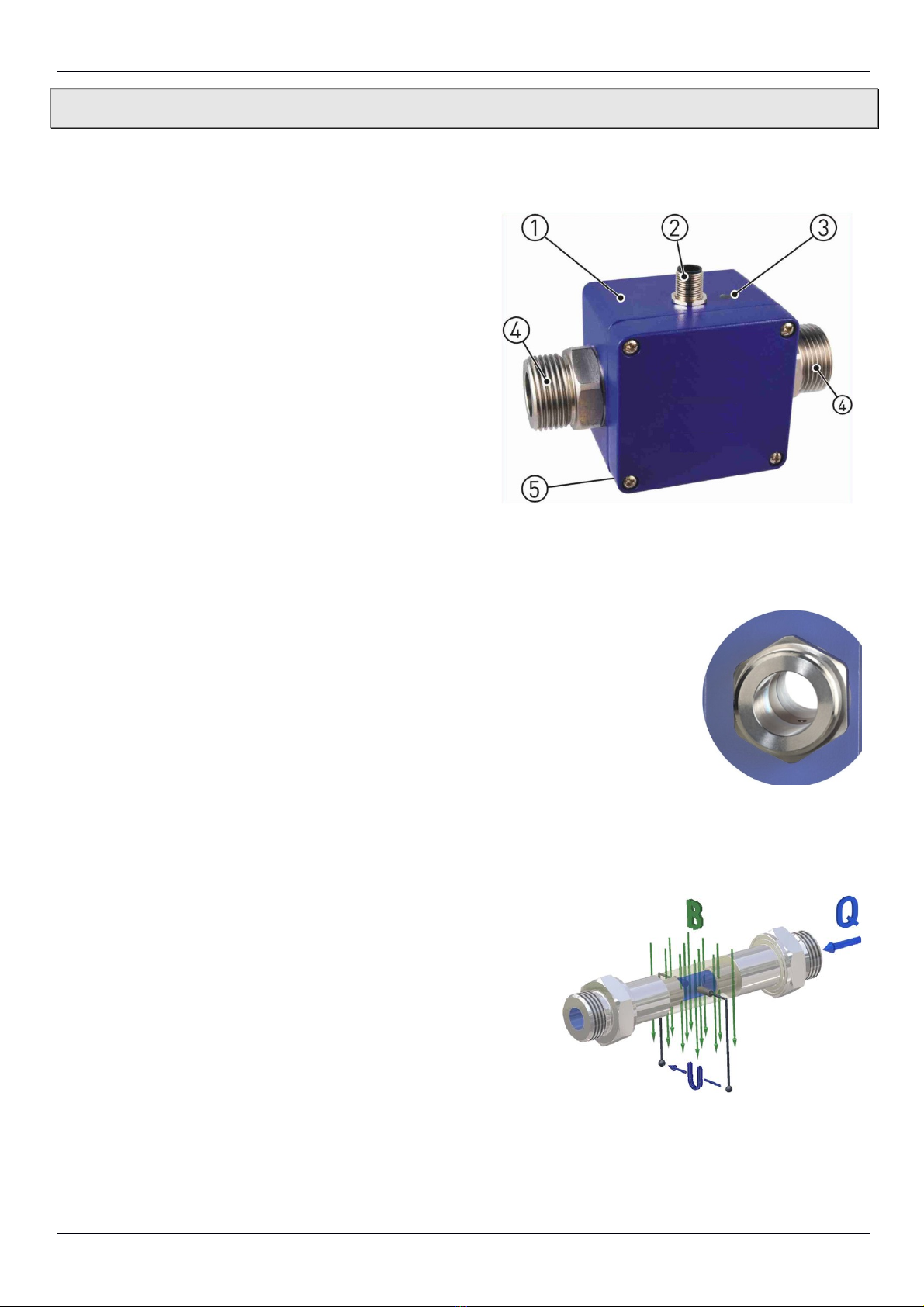
Components:
Housing:
The housing consists of aluminium die casting and
has the IP65 degree of protection.
Electrical connection:
The electrical connection is made via 5-pin plug
M12x1.
Operation / flow indicator LED.
Process connection:
The process connections are available in different
sizes.
T pe plate (sticker).
Construction:
The measuring tube with its earthing sleeves and electrodes passes through the
housing and forms the external process connection of the DM04.
A magnetic field for the measurement process is generated inside the sensor hous-
ing, which also contains the sensor and signal conditioning circuitr .
The two stainless steel electrodes are located in the middle of the measuring tube
between the earthing sleeves.
The DM04 does not need an moving parts to make measurements. The inside of
the measuring tube is completel open, allowing the fluid to flow unhindered
through the measuring tube.
Function:
The magnetic inductive flow sensor operates in accordance with the principle of induction, i.e. a DC voltage
is generated b the movement of a conductor in a magnetic field:
The measuring tube of the DM04 is located in a magnetic
field (B).
An electricall conductive liquid (Q) flows through the measur-
ing tube. The positive and negative charge carriers are deflected
in opposite directions.
A voltage perpendicular to the magnet field is generated and
picked up b the two electrodes.
The resulting induced voltage is proportional to the mean flow
velocit of the liquid.
The electronics of the DM04 converts the induced voltage to a
flow-proportional frequenc signal.
- 6 - PKP Prozessmesstechnik • 08/2019

Instruction Manual DM04
4 Installation of DM04
Before installing, check that
the wetted materials of the device are suitable for the liquid being used (§ 9.2 “Materials table”).
the equipment is switched off and is in a safe and de-energised state.
the equipment is depressurised and has cooled down.
SUITABLE TOOLS:
Use onl suitable tools of the correct size.
4.1 Installation instructions
CAUTION! isk of malfunction due to external magnetic fields!
Magnetic fields close to the device can cause malfunctions and should be
avoided.
Ensure that no external magnetic fields are present at the installation
site of the DM04.
The DM04 can alwa s be installed an where along the pipeline. Straight sections of piping are prefer-
able, however.
- 7 - PKP Prozessmesstechnik • 08/2019

Instruction Manual DM04
Installation can occur in horizontal and vertical pipes. The flow sensor is onl suitable for application in
completel filled pipe s stems.
As a matter of principle magnetic inductive flow sensors are widel independent from the flow profile.
An inlet section is not absolutel necessar .
To reach a most highl accurac of the measurement, ou should use straight inlet and outlet sections
according to the nominal width (DN). The inlet section has to be at least 10 x DN; the outlet section
5 x DN in order to achieve the specified accurac .
The inlet and outlet sections and the gaskets must have the same or a slightl larger inside diameter than
the measuring tube in order to achieve the specified accurac .
4.2 Mounting
The DM04 is installed directl into the pipeline. The compact design and light weight of the unit make wall-
mounting unnecessar .
IMPORTANT NOTICES:
Onl use suitable gaskets for installation.
Observe the flow direction indicated on the DM04.
Observe the mounting dimensions (§ 9.5 “Dimensions”).
Select an appropriate location for installation (§ 4.1 “Installation in-
structions”).
To ensure the best possible measuring accurac , a vertical installation
position with increasing flow is preferable (no collecting of dirt depos-
its).
Install the appropriate screwed connections at the installation location.
Insert the DM04 together with the gaskets.
Screw the union nuts of the screwed connection onto the process con-
nections of the DM04.
CAUTION! Material damage!
Pay attention to maximum torque.
While tightening, counter the union nut on the hexagon of the pro-
cess connection!
If ou do not counter it, the DM04 can be damaged!
Maximum Torque
DM04.1 - G½ DM04.2/3 – G½ • G¾ DM04.4 - G1
15 Nm 15 Nm 30 Nm
Tighten both union nuts.
When tightening, use a spanner (AF 27 or AF 34) to counter the pro-
cess connection on the hexagon in place.
- 8 - PKP Prozessmesstechnik • 08/2019

Instruction Manual DM04
5 Electrical connection
The electrical connection of the DM04 is via the 5-pin plug M12x1 at the top of the housing.
The wiring of the DM04 depends on the ordered version. A distinction is made between frequenc and ana-
logue output, as well as basic and optional wiring.
CAUTION! Electric current!
The electrical connection should onl be carried out b a full qualified electrician.
De-energize the electrical s stem before connecting the DM04.
CAUTION! Material damage and fire hazard!
Exceeding the specified limits will cause damage to the electronics. Without current limiting, there is
a fire hazard due to overheating of the device.
Connect the DM04 onl to a power source with limited power.
Optional wirings:
Depending on the version, an analogue output can be optionall connected.
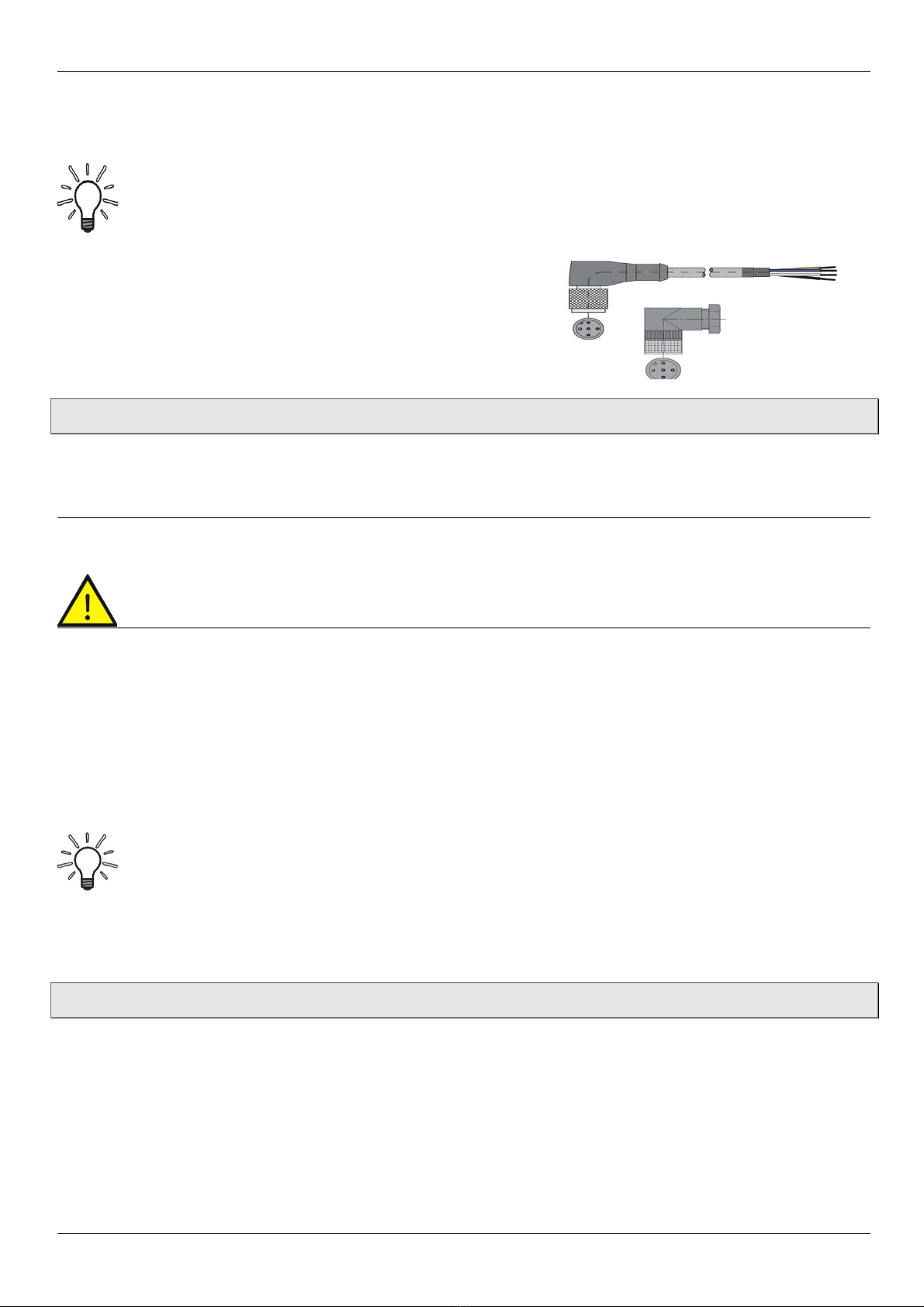
Connecting cable:
Suitable connection cables with moulded coupling socket are available in various lengths included in the
range of SIKA accessories. The shielding is alread connected
with the knurled nut.
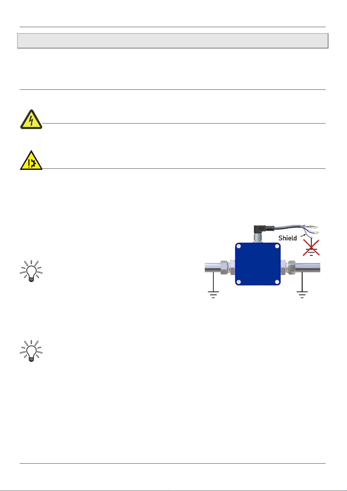
IMPORTANT! Shielding required!
Use onl shielded connection cables.
The shield of the connection cable should not
be connected to earth.
We recommend to earth the pipes directl before and behind the
DM04 ( Figure).
IMPORTANT NOTICE:
Pa attention to the temperature resistance of the connecting cable (§ 9 “Technical data) at high me-
dia temperatures.
If the temperature resistance is smaller than the medium temperature, the cable ma not be directl
laid on the pipe.
Connection 5-pin plug M12x1:
Screw the coupling socket of the connection cable to the plug of the DM04.
Tighten the knurled nut of the coupling socket with a maximum torque of 1 Nm.
- 9 - PKP Prozessmesstechnik • 08/2019
Inhaltsverzeichnis
Andere PKP Messgerät Handbücher

PKP
PKP PMR06 Bedienungsanleitung

PKP
PKP DS02.1 Bedienungsanleitung

PKP
PKP DS05 Bedienungsanleitung

PKP
PKP DTL06 Bedienungsanleitung

PKP
PKP DV08 Bedienungsanleitung

PKP
PKP DS08 Bedienungsanleitung

PKP
PKP DB51 Bedienungsanleitung

PKP
PKP DOZ03 Bedienungsanleitung

PKP
PKP DP07 Bedienungsanleitung

PKP
PKP DS07 Bedienungsanleitung

PKP
PKP DM01A Bedienungsanleitung

PKP
PKP DB04A Bedienungsanleitung

PKP
PKP DS20 Bedienungsanleitung

PKP
PKP PMR06 Bedienungsanleitung

PKP
PKP DR15 Bedienungsanleitung

PKP
PKP DS10 Series Bedienungsanleitung

PKP
PKP DVO1 Bedienungsanleitung

PKP
PKP DS25 Bedienungsanleitung

PKP
PKP DS11 Bedienungsanleitung

PKP
PKP DG03 Bedienungsanleitung