
PKP DND01.01 Series Bedienungsanleitung
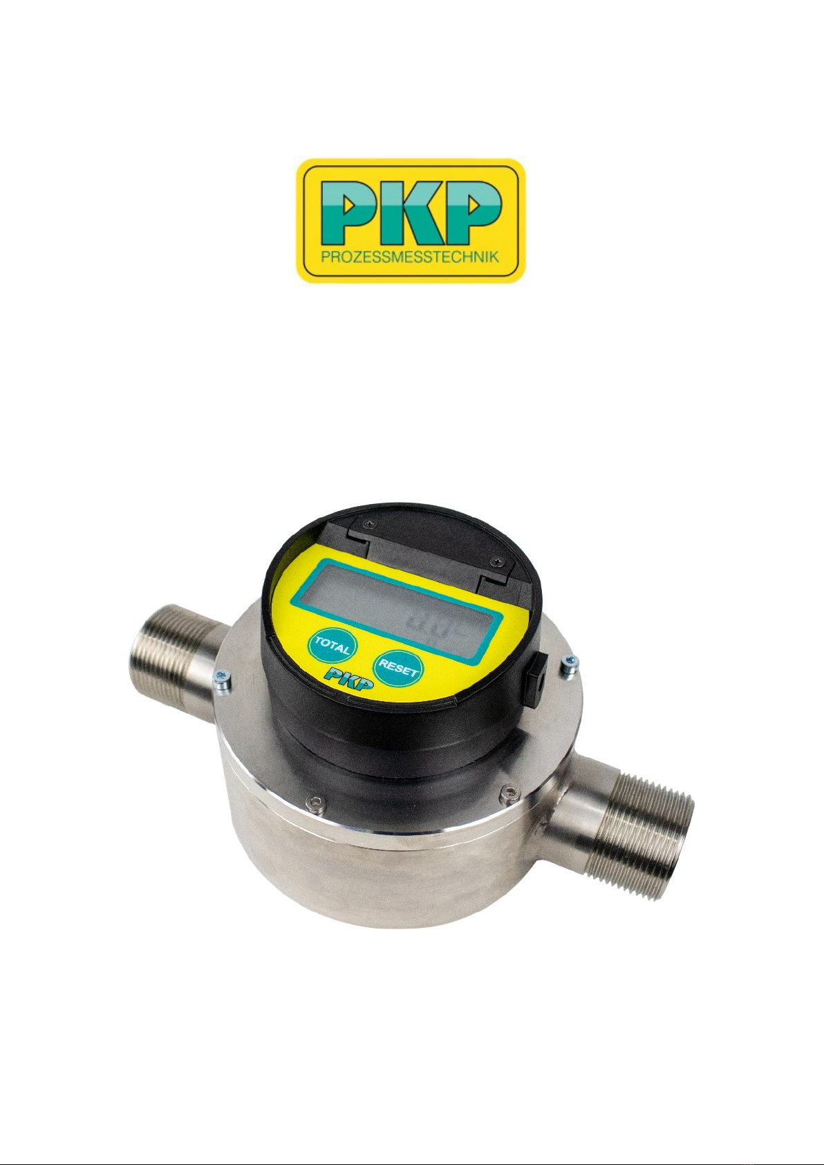
Instruction Manual
DND01
Nutating Disc Meter
PKP Prozessmesstechnik GmbH
Borsigstraße 24
D-65205 Wiesbaden- ordenstadt
Tel.: ++49-(0)6122-7055-0
Fax: ++49-(0)6122-7055-50
Email: [email protected] www pkp.de

Table of Contents
Safety Information..................................................................................................................2
Installation..............................................................................................................................3
Putting into operation.............................................................................................................4
Evaluation units general.........................................................................................................5
Electrical Connection / Evaluation units................................................................................6
Function of the on-site display.............................................................................................12
Programming of the on-site display.....................................................................................14
Linearisation.........................................................................................................................18
Additional programming of more parameters for display with pulse and analogue output
(Type B and D2)...................................................................................................................19
Cleaning...............................................................................................................................22
Safety Information
General Instructions
To ensure safe operation, the device should only be operated according to the
specifications in the instruction manual. The requisite Health & Safety regulations for a
given application must also be observed. This statement also applies to the use of
accessories.
Every person who is commissioned with the initiation or operation of this device must have
read and understood the operating instructions and in particular the safety instructions!
The work safety instructions in this manual as well as the safety, accident prevention and
environmental protection regulations generally valid for the work area must be observed.
The liability of the manufacturer expires in the event of damage due to improper use, non-
observance of this operating manual, use of insufficiently qualified personnel and
unauthorized modification of the device.
Proper Usage
The nutating disc flow meters D D01 are designed to monitor continuous flow rates of
liquids or gases which do not attack the device materials. All other usage is regarded as
being improper and outside the scope of the device.
In particular, applications in which shock loads occur (for example, pulsed operation)
should be discussed and checked in advance with our technical staff.
The series D D01 flow meter devices should not be deployed as the sole agents to
prevent dangerous conditions occurring in plant or machinery. Machinery and plant need
to be designed in such a manner that faulty conditions and malfunctions do not arise that
could pose a safety risk for operators.
Dangerous substances
For dangerous media such as e.g. Oxygen, Acetylene, flammable or toxic substances as
well as refrigeration systems, compressors, etc. must comply with the relevant regulations
beyond the general rules.
D D01 Instruction manual 03/2023 page 2

Qualifie Personnel
The D D01 devices may only be installed by trained, qualified personnel who are able to
mount the devices correctly. Qualified personnel are persons, who are familiar with
assembling, installation, placing in service and operating these devices and who are
suitably trained and qualified.
Inwar Monitoring
Please check directly after delivery the device for any transport damages and deficiencies.
Additional with reference to the accompanying delivery note the number of parts must be
checked.
Claims for replacement or goods which relate to transport damage can only be considered
valid if the delivery company is notified without delay.
Installation
Before the first installation:
Please flush the meter with fresh water or the medium to measure before the first
installation.
Before installing a meter in a new or modified pipework, the complete pipe system should
be cleaned to remove any impurity like solder, sealing material, welding beads, etc. Inlet
and outlet straight pipe runs are not necessary.
All mounting positions are possible.
Install the meter in such a way that no stress nor strain does effect the meter housing in
order to avoid any damage of threads and/or meter housing. Make sure that the arrow on
the meter housing shows in flow direction.
In case a solenoid valve is used in connection with very frequent switching cycles, the
valve should be mounted on the inlet side of the meter in order to avoid pressure shocks.
To maintain fullpipe conditions, a non-return valve may be mounted at the outlet. To
ensure an exact measurement, please make sure that the measuring chamber is always
fully filled.
Do not place the device on an unstable place where it could fall.
ever place the device near a radiator.
Keep cables away from potential hazards.
Ground the device before installation.
D D01 Instruction manual 03/2023 page 3

Putting into operation
As with any fine instrument, care must be taken in the installation. Your particular meter
may be of special design and may require special information, however, these tips cover
several points of concern with all models.
Please verify the following prior to installation and operation.
Yes o
— Has the piping system been cleaned and is free
of any dirt and particles?
— Has a strainer been installed at the inlet of the
meter? (only for P series)
— Is mounting position as per requirement?
— Is flow direction in accordance with the arrow
marking?
— Is operating flow within specifications? (The
maximum specified flow rate is an instrument
maximum design flow rate and is not
recommended for continuous operation. For
optimum performance a continuous flow rate
should not exceed 65% of design maximum)
— Is material compatibility verified and confirmed?
— Is operating pressure within limits?
— Have measures been taken, in case of low
viscous fluids, that the pressure drop across
the meter does not exceed 1.0 bar?
— Is operating temperature within limits?
— Have measures been taken to avoid pressure
shocks? In case a solenoid valve is used in
connection with very frequent switching cycles,
the valve should be mounted on the inlet of the
meter. To maintain full pipe conditions a non-
return valve may be mounted at the outlet.
— Does wiring comply with attached wiring
diagram?
— Have you carefully read the operating manual?
Begin start-up only once you have answere all questions with YES.
When putting into operation, always open the upstream valve slowly to apply with the fluid
pressure of the meter and avoid any pressure shocks.
Please make sure that the following parameters are always observed:
a) Maximum operating pressure is 16 bar for the M-series and 10 bar for the P-series.
b) Maximum operating temperature is 50 °C for plastic meters and 120 °C for
bronze meters with LCP chamber.
c) Meters must always be operated within the specified flow range.
d) Maximum pressure drop across the meter is 1 bar for low viscous fluids and 3,4 bar
for liquids up to maximum 800 mPas.
D D01 Instruction manual 03/2023 page 4

Evaluation units general
Features:
Large, six-digit LCD display
Display in litres, pints, quarts or gallons freely programmable
11-digit non-resettable totaliser and 6-digit resettable totaliser
Replaceable battery with long life
Stored calibration factor
9-point linearisation
Scalable pulse output (with output signal code B and option D2)
4-20 mA output (for output signal code B and option D2)
Protection class: IP65
Description:
The electronic evaluation unit (register) consists of a microprocessor board powered by a
lithium battery. It can be programmed in litres, pints, quarts or gallons and adds in litres or
gallons.
A calibration factor and a unit of measure are programmed during a factory test. Unlike
mechanical units, these can be electronically recalibrated in the field if necessary. A 6-digit
LC display with three decimal places shows the exact amount of liquid flowing through the
meter. The register is protected from normal wear and tear by a robust, shockproof
housing.
Operation:
The magnets integrated in oval gear counters send pulses to the register.
The register is in sleep mode until pulses arrive. The pulses are generated by the liquid
flowing through the meter.
The register shows the current flow rate, the subtotal and the total.
The resettable totaliser has a 6-digit display with three digits after the decimal point. If the
measured quantity exceeds 999.999, the display jumps over. Then only 2 digits behind the
decimal point 9999.99 are displayed and so on up to the maximum value of 999999. After
999999 is reached, the totaliser starts again with 0.000. When the reset button is pressed,
the totaliser is reset to zero. The register also has a resettable total counter. To reset this,
the total and reset keys must be pressed simultaneously ("Total" key pressed and held,
"Reset" key pressed). This can be used for several subtotals.
The non-resettable totalisers have 11 digits and count arbitrarily in either gallons or litres.
D D01 Instruction manual 03/2023 page 5
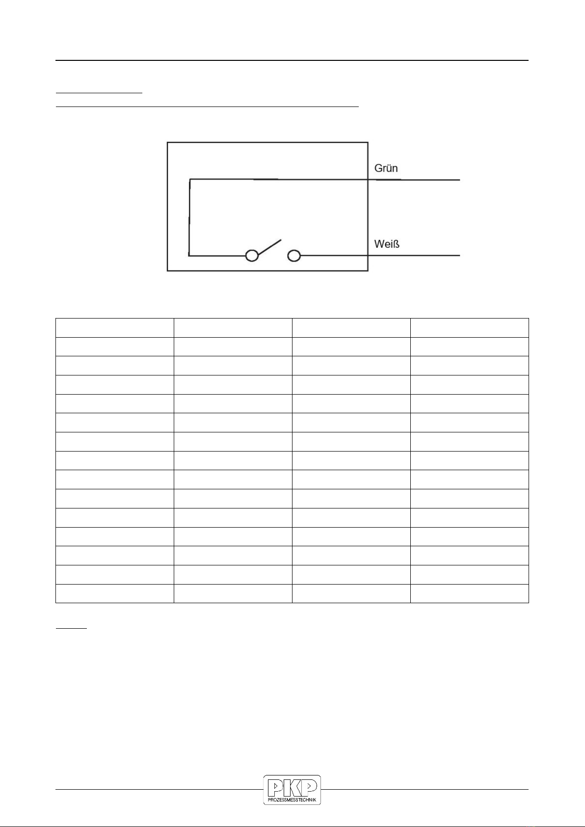
Electrical Connection / Evaluation units
DND01, Co e R
potential free Ree contact, pulse output, 2,7 m cable:
Connection plan:
Pulse per unit of measure
Model Connection Pulses/litre Pulses/Gallon
D D01.01…. 3/4“ male 52,4 198,3
D D01.02…. 1“ male 52,4 198,3
D D01.03…. 3/4“ male 52,4 198,3
D D01.04…. 1“ male 52,4 198,3
D D01.05…. 3/4“ male 52,4 198,3
D D01.06…. 1“ male 52,4 198,3
D D01.08…. 1“ male 52,4 198,3
D D01.09…. 1 1/4“ male 23,7 89,8
D D01.10…. 1 1/4“ male 23,7 89,8
D D01.11…. 1 1/4“ male 12,3 46,8
D D01.12…. 1 1/4“ male 12,3 46,8
D D01.13…. 1 1/2“ female PT 6,3 23,9
D D01.14…. 1 1/2“ female PT 6,3 23,9
D D01.15…. 2“ female PT 3,8 14,6
Note:
Pulses per liter are shown unit-specifically on the calibration certificate
supplied and on the type plate.
D D01 Instruction manual 03/2023 page 6
white
green
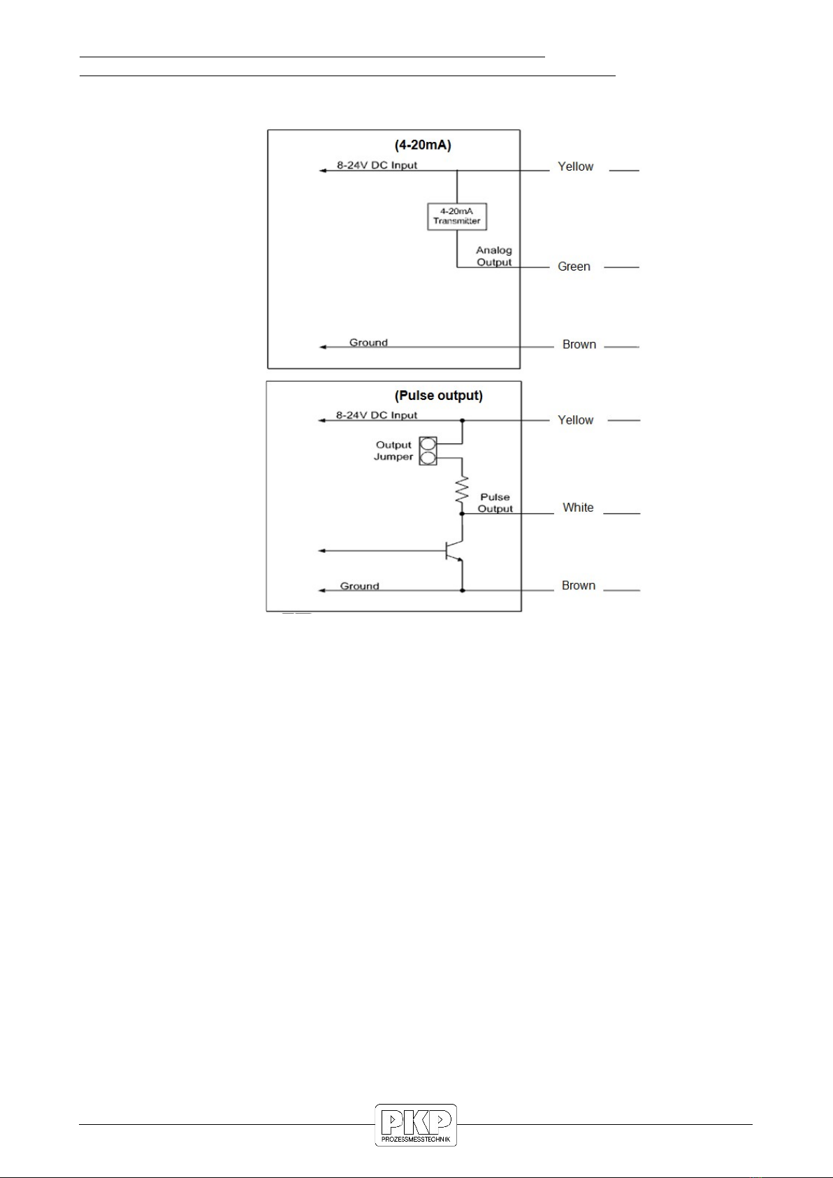
On Site Display (mounte or seperate), Pulse output NPN,
Analoge output (4...20 mA), 3 m cable, or er co e B or Option D2
Connection plan:
egister wiring
External DC+ : Yellow
External ground : Brown
Pulse output : White
Analog output : Green
DC input : 8 to 24 VDC; 20 to 40 mA
Outputs:
- Analogue 4 to 20 mA output in loop powered configuration; external load of 50
ohms to 250 ohms; flow rate is linear scaled between 4 mA minimum and 20 mA
maximum set points; flow rates below programmed minimum read 4 mA.
- Pulse output with internal pull-up resistor (10 KΩ); optional open collector output
with output jumper removal; pulse output is scalable in pulses per liter or pulses
per gallon.
D D01 Instruction manual 03/2023 page 7
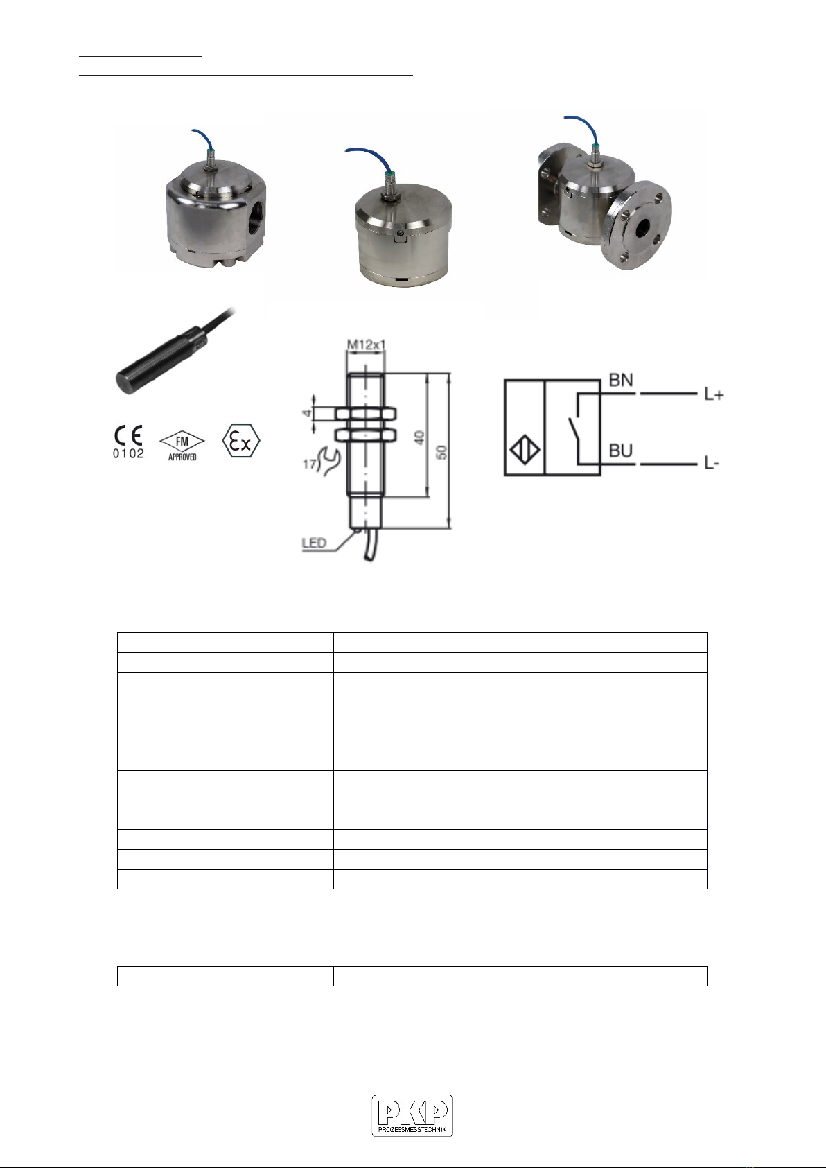
DND01, Co e M
NAMUR Pulse output, unscale , 2 m cabel
Technical data:
Switching function ormally open ( O)
Output type AMUR 2-wire
ominal voltage Uo 8,2 V (Ri ca. 1 kΩ)
Effective internal
inductivity
Ci ≤ 15 nF; a cable length of 10m is
considered
Effective internal
inductance
Li ≤ 35 µH; a cable length of 10m is
considered
Switch state indicator LED (yellow)
Ambient temperature -25 to 70°C (-13 to 158°F)
Cable length 2 meters (PVC)
Core cross-section 0,34 mm²
Material Stainless steel 1.4404 (316L)
Protection class IP66 / IP67
Marking:
amur CE 0102 / Ex II2G Ex ib IIC T6 Gb
D D01 Instruction manual 03/2023 page 8

Pulse per unit of measure
Model Connection Pulses/litre Pulses/Gallon
D D01.01…. 3/4“ male 52,4 198,3
D D01.02…. 1“ male 52,4 198,3
D D01.03…. 3/4“ male 52,4 198,3
D D01.04…. 1“ male 52,4 198,3
D D01.05…. 3/4“ male 52,4 198,3
D D01.06…. 1“ male 52,4 198,3
D D01.08…. 1“ male 52,4 198,3
D D01.09…. 1 1/4“ male 23,7 89,8
D D01.10…. 1 1/4“ male 23,7 89,8
D D01.11…. 1 1/4“ male 12,3 46,8
D D01.12…. 1 1/4“ male 12,3 46,8
D D01.13…. 1 1/2“ female PT 6,3 23,9
D D01.14…. 1 1/2“ female PT 6,3 23,9
D D01.15…. 2“ female PT 3,8 14,6
Note:
Pulses per litre are shown unit-specifically on the calibration certificate
supplied and on the type plate.
D D01 Instruction manual 03/2023 page 9
white
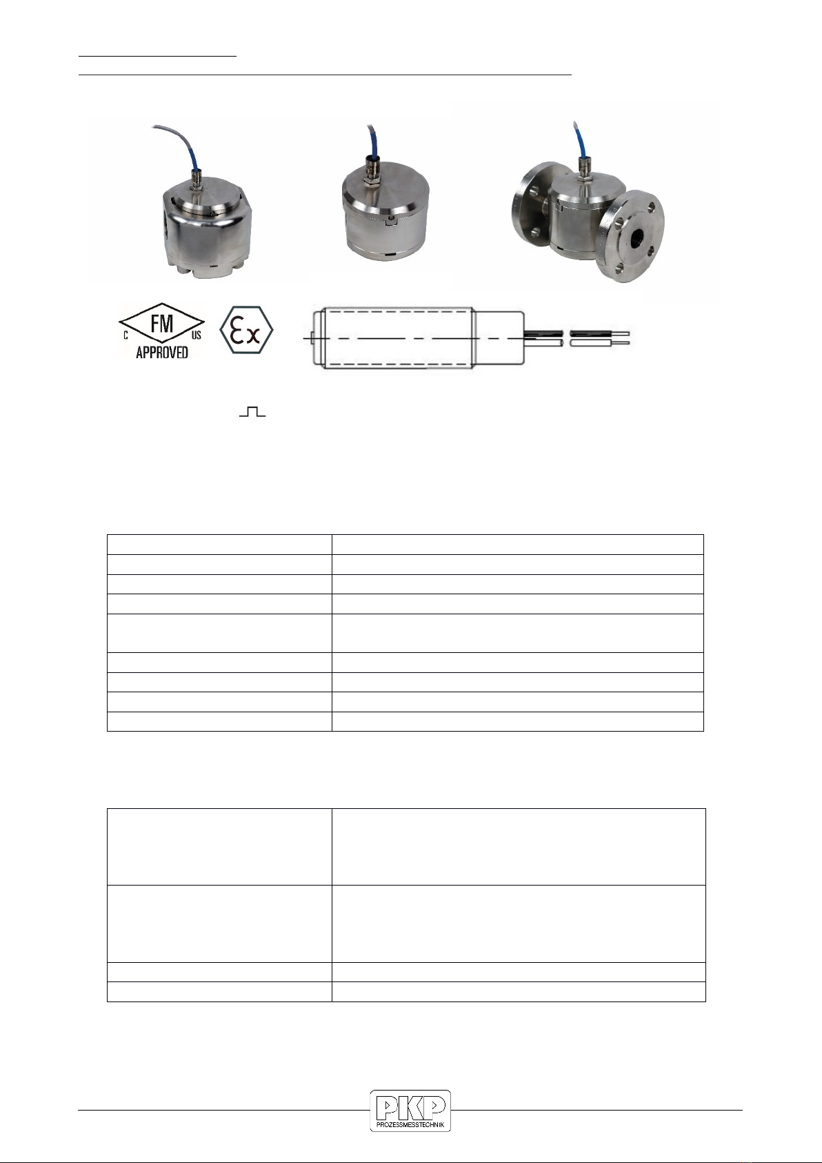
DND01, Co e P or N
PNP or NPN pulse output, Open Collector, unscale , 3 m cabel
Connection: white
red (+)
black (-)
Technical data:
Switching function Open collector
Output type P or P P 3-wire (2 versions available)
Supply voltage 5-30 VDC (I ≤ 15 mA)
Supply current 100 mA max ( Pmax = 0,66 watt)
Effective internal
inductivity
Ci ≤ 12 nF
Effective internal inductance Li ≤ 0 µH
Cable length 3 meters
Material Stainless steel 1.4404 (316L)
Protection class IP66 / IP67
Marking:
USA Intrinsically safe
Class I, II, III, Division 1
GROUP ABCDEFG T6 to T5
Class I, Zone 0, AEx ia IIC T6 to T5
Canada Intrinsically safe
Class I, Division 1
GROUP ABCD T6 to T5
Class I, Zone 0, Ex ia IIC T6 to T5
ATEX Ex II 1G Ex ia IIC T6 to T4 Ga
IIECEx Ex ia IIC T6 to T4 Ga
D D01 Instruction manual 03/2023 page 10
Dieses Handbuch passt für folgende Modelle
14
Inhaltsverzeichnis
Andere PKP Messgerät Handbücher

PKP
PKP DOZ03 Bedienungsanleitung

PKP
PKP DM04 Bedienungsanleitung

PKP
PKP DS07 Bedienungsanleitung

PKP
PKP PMR06 Bedienungsanleitung

PKP
PKP DV08 Bedienungsanleitung

PKP
PKP DR15 Bedienungsanleitung

PKP
PKP DS11 Bedienungsanleitung

PKP
PKP DS25 Bedienungsanleitung

PKP
PKP DS15 Bedienungsanleitung

PKP
PKP DB04A Bedienungsanleitung

PKP
PKP DS10 Series Bedienungsanleitung

PKP
PKP PMR06 Bedienungsanleitung

PKP
PKP DP05 Bedienungsanleitung

PKP
PKP DP07 Bedienungsanleitung

PKP
PKP DVO1 Bedienungsanleitung

PKP
PKP DS05 Bedienungsanleitung

PKP
PKP DS03 Bedienungsanleitung

PKP
PKP DS09 Bedienungsanleitung

PKP
PKP DG03 Bedienungsanleitung

PKP
PKP DU06 Series Bedienungsanleitung


