Plux biosignalsplux Light Bedienungsanleitung

biosignal acquisition tool-kit for advanced research applications
Light (LUX) Sensor User Manual

Light (LUX)
User Manual
PLUX –Wireless Biosignals, S.A.
Av. 5 de Outubro, n. 70 –2.
1050-059 Lisbon, Portugal
http://biosignalsplux.com/
v.1.0
© 2020 PLUX
This information is provided "as is," and we make no express or implied warranties whatsoever with respect to functionality, operability, use, fitness for a
particular purpose, or infringement of rights. We expressly disclaim any liability whatsoever for any direct, indirect, consequential, incidental or special
damages, including, without limitation, lost revenues, lost profits, losses resulting from business interruption or loss of data, regardless of the form of action or
legal theory under which the liability may be asserted, even if advised of the possibility of such damages.
ATTENTION
Please read this datasheet before
using your biosignalsplux sensor
The information contained in this document has been carefully checked and were made every effort
to ensure its quality. PLUX reserves the right to make changes and improvements to this manual and
products referenced at any time without notice.
The word Bluetooth and its logo are trademarks of Bluetooth SIG Inc. and any use of such marks is
under license. Other trademarks are the property of their respective own.
Please check your systems and sensors after receiving and before using it the first time to confirm if it
contains all the ordered sensors, accessories and other components. Contact our support via e-mail at
For regulatory information, please see the Regulatory Disclaimer at the end of this document.

Light (LUX)
User Manual
3 of 17
TABLE OF CONTENTS
1. General Information............................................................................................................. 4
1.1. General Description ........................................................................................................... 4
1.2. Typical Unfiltered Sensor Output........................................................................................ 4
1.3. Sensor Specifications ......................................................................................................... 5
1.4. Features ............................................................................................................................ 5
1.5. Applications....................................................................................................................... 5
1.6. Transfer Function (Conversion Formula)............................................................................. 5
1.7. Electrode Connections & Sleeve Color Meanings....................... Error! Bookmark not defined.
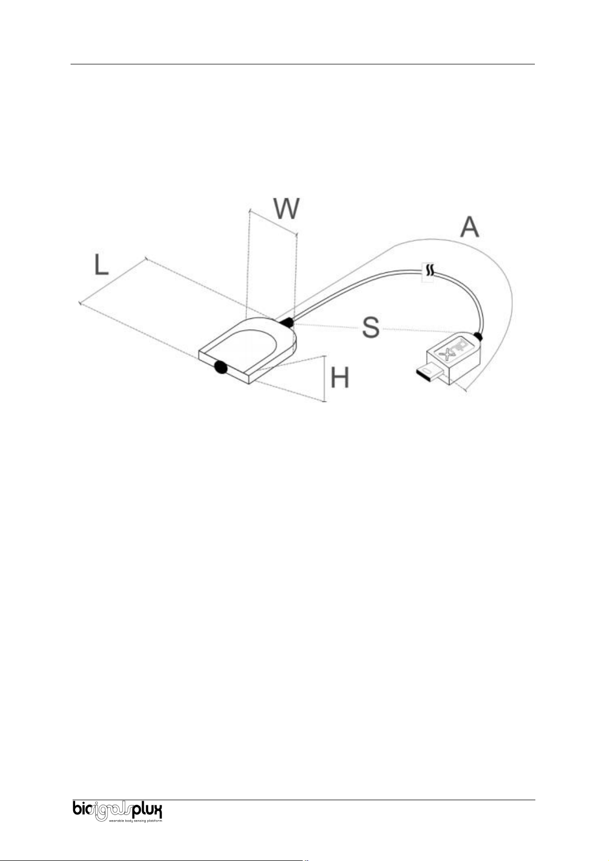
1.8. Physical Characteristics...................................................................................................... 6
2. Application Notes..................................................................................................................... 7
2.1. Sensor Placement .............................................................................................................. 7
3. Using the Light (LUX) Sensor with biosignalsplux & OpenSignals ................................................ 8
3.1. Connecting the sensor to biosignalsplux Systems................................................................ 8
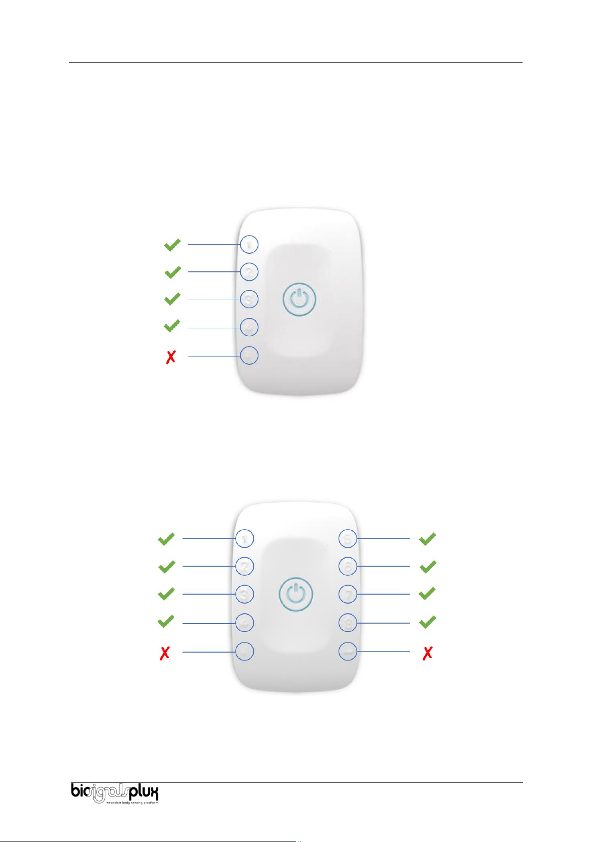
3.1.1. biosignalsplux 4-Channel Hubs............................................................................................. 8
3.1.2. biosignalsplux 8-Channel Hubs............................................................................................. 8
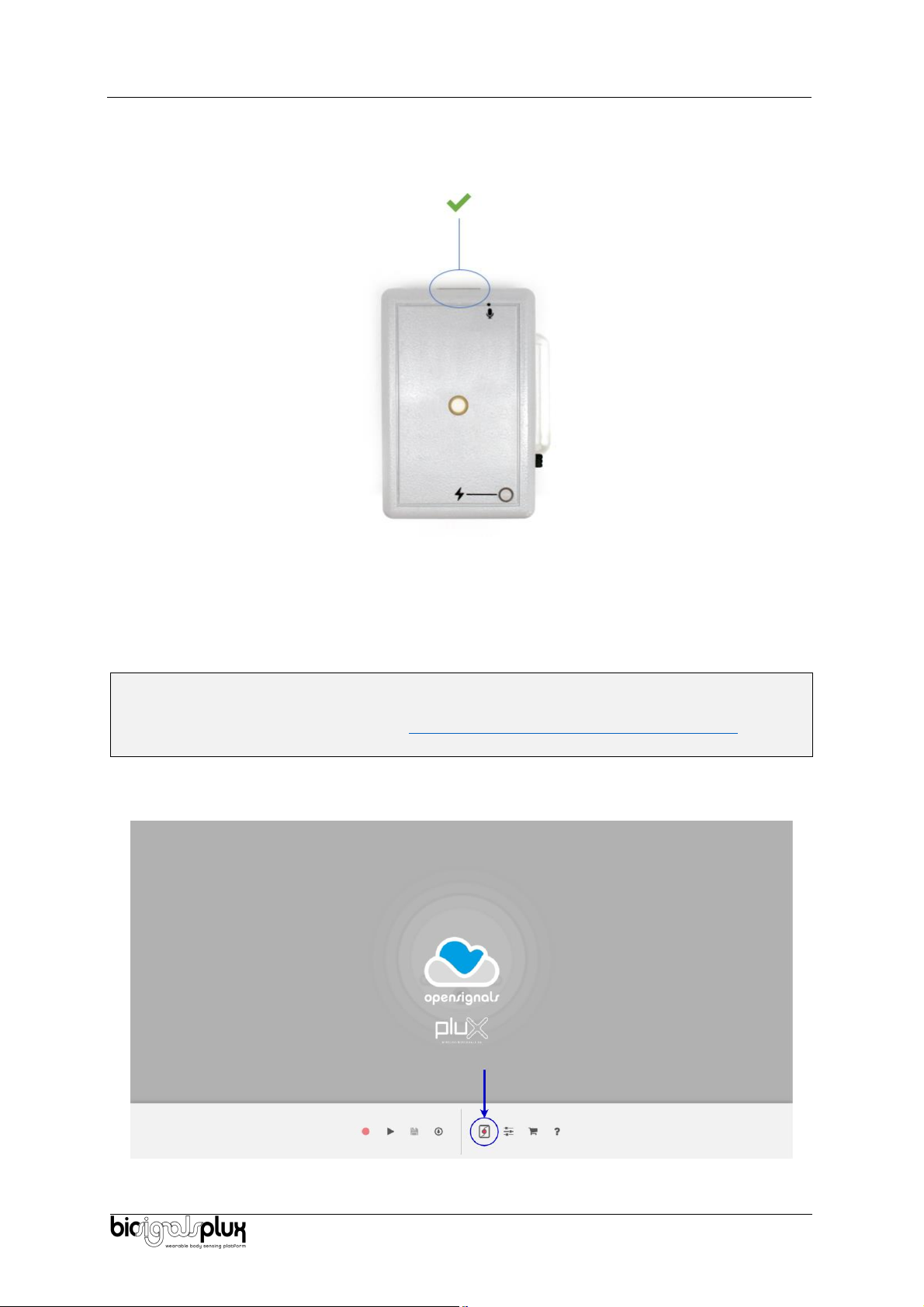
3.1.3. biosignalsplux Solo & Single-Channel openBAN Devices ..................................................... 9
3.2. Configuring the Sensor in OpenSignals................................................................................ 9
3.2.1. OpenSignals (r)evolution (Windows, macOS, Linux) ............................................................ 9
4. Scientific Publications Using the Light (LUX) Sensor ................................................................. 12
5. Safety & Maintenance ............................................................................................................ 13
5.1. Safety Instructions........................................................................................................... 13
5.2. Transportation and Storage.............................................................................................. 14
5.3. Cleaning .......................................................................................................................... 14
6. Ordering Guides, Regulatory & Legal Information.................................................................... 15
6.1. Ordering Guide................................................................................................................ 15
6.2. Guarantee of Quality & Warranty..................................................................................... 15
6.3. Warranty Voidance.......................................................................................................... 15
6.4. Contact & Support ........................................................................................................... 16
6.5. Regulatory Disclaimer...................................................................................................... 16
6.6. Document Version Tracking ..................................................... Error! Bookmark not defined.

Light (LUX)
User Manual
4 of 17
1. General Information
1.1. General Description
Our Light (LUX) sensor has been especially designed for the synchronization of the recorded data with
external sources (e.g. a computer screen for visual evoked potentials). If applied to the computer
screen, our LUX sensor can be used to detect chromatic changes in the stimuli, hence providing a
synchronization source. The LUX sensor can also be useful for optical synchronization with third-party
devices (provided that the third-party device can trigger a LED), in applications where it is important
to have electrical decoupling between devices.
In addition, Light (LUX) sensor can be used for the specific purpose of tracking physiological responses
(e.g. heart rate) in dependence of the ambient light changes or visual evoked potentials.
Figure 1: biosignalsplux Light (LUX) sensor (standard version).
1.2. Typical Unfiltered Sensor Output
Figure 2 shows a typical unfiltered LUX sensor output acquired while light changes. The raw digital
sensor values received from the biosignalsplux device ranged between 0 and 2n-1 (n=sampling
resolution) and were normalized into values between 0 and 1 using the transfer function found in
section Transfer Function (Conversion Formula).
Figure 2: Typical unfiltered LUX sensor output while light change.

Light (LUX)
User Manual
5 of 17
1.3. Sensor Specifications
> Range:
400-700 nm
[550 nm | peak spectral wavelength]
> Consumption:
~0.05 mA
1.4. Features
>Pre-conditioned analog output
> Small form factor
>High signal-to-noise ratio
> Easy-to-use
> Raw data output
1.5. Applications
> Synchronization with a computer screen
> Ambient light monitoring
> Optical marker detector
1.6. Transfer Function (Conversion Formula)
The analog sensor signals acquired with biosignalsplux devices are converted into digital values ranged
between 0 and 2n-1 (n=sampling resolution, usually 8-bit or 16-bit) and streamed in the raw digital
format.
In most applications, a value between 0 and 1 describes the detection of light appearance of the
acquired LUX signal well, therefore a normalization is performed:
𝐿𝑈𝑋(−) = ADC
2n - 1
(1)
Valid sensor range: [0, 1]
with: 𝐿𝑈𝑋(−)LUX normalized value
𝐴𝐷𝐶 Value samples from the sensor/channel (digital value)
𝑛Sampling resolution (default: 16-bit resolution (n=16), although 12-bit
and 8-bit may also be found)
The previous normalized value can be converted to a percentual metric through a simple multiplication
by the product factor 100%.
𝐿𝑈𝑋(%)= 𝐿𝑈𝑋(−)×100%

Light (LUX)
User Manual
6 of 17
1.7. Physical Characteristics
> W x L x H:
1.6cm x 2.2cm x 0.5cm
> A:
105.0±0.5cm
> S:
30±0.1cm
> Available sleeve colors:
White, Black, Blue, Green, Red, Yellow, Grey, and Brown
Sensor also available with Adimension equal to 30cm cable length. For custom lengths, please
Figure 3: Physical characteristics of the standard Light (LUX) sensor.

Light (LUX)
User Manual
7 of 17
2. Application Notes
The biosignalsplux light (LUX) is designed for the detection of ambient light for synchronization of
recorded data with external sources such as the computer screen (visual evoked potentials).
2.1. Sensor Placement
The illustration shown in Figure 4 shows a possible sensor placement for the acquisition of ambient
light detection (screen of laptop).
Figure 4: biosignalsplux light (LUX) sensor applied to computer screen
After placing the LUX sensor in the desired location, connect the device with the biosignalsplux hub,
as described in the following chapter 3.

Light (LUX)
User Manual
8 of 17
3. Using the Light (LUX) Sensor with biosignalsplux & OpenSignals
3.1. Connecting the sensor to biosignalsplux Systems
3.1.1. biosignalsplux 4-Channel Hubs
The biosignalsplux LUX sensor is compatible with all 4 analog input channels of the 4-channel
biosignalsplux hub, but incompatible with the reference/ground port. Connect the sensor the analog
input to use it with this device.
Figure 5: LUX compatible biosignalsplux channels (green checkmarks).
3.1.2. biosignalsplux 8-Channel Hubs
The biosignalsplux LUX sensor is compatible with all 8 analog input channels of the 8-channel
biosignalsplux hub, but incompatible with the reference/ground and digital I/O ports. Connect the
sensor to an analog input to use it with this device.
Figure 6: LUX compatible biosignalsplux channels (green checkmarks).

Light (LUX)
User Manual
9 of 17
3.1.3. biosignalsplux Solo & Single-Channel openBAN Devices
The biosignalsplux LUX sensor is compatible with the analog input channel of the biosignalsplux Solo
(openBAN) device. Connect the sensor to the analog input channel to use it with this device.
Figure 7: Connect the LUX to the analog input channel of the biosignalsplux Solo (openBAN).
3.2. Configuring the Sensor in OpenSignals
3.2.1. OpenSignals (r)evolution (Windows, macOS, Linux)
Note
Download OpenSignals (r)evolution here: https://biosignalsplux.com/index.php/software
Open the OpenSignals (r)evolution device manager to access and configure your biosignalsplux
device.
Figure 8: Access the OpenSignals (r)evolution device manager.

Light (LUX)
User Manual
10 of 17
Select the device you intend to use for acquisition by clicking on ENABLE button on the device panel in
the OpenSignals device manager. The device is activated for acquisition if the ENABLE button is blue.
Figure 9: Enabling the device for acquisition.
Click on the biosignalsplux logo to access the available settings. Select the channel your sensor is
connected to and select the RAW from the dropdown menu highlighted in the next screenshot.
Figure 10: Set the channel type of the channel you have your LUX sensor connected to, to RAW.
Activate the channel for acquisition by clicking on the circle next to the channel type (must be blue). If
not done before, follow the instructions available in section 2 Application notes to learn how to apply
the sensor and 3.1 Connecting the sensor to biosignalsplux Systems to learn how to connect your
device to your biosignalsplux device. Click on the record button in the OpenSignals main interface
whenever you’re ready for your acquisition.
Inhaltsverzeichnis
Andere Plux Zubehör Handbücher


