
SWR Envea M-Sens 2 Bedienungsanleitung

EN
M-Sens 2
Online moisture measurement
for solids
Operating Instructions
M-Sens 2
Online moisture measurement
for solids
SWR engineering Messtechnik GmbH PART OF THE ENVEA GROUP

2
CONTENTS Page
1. System overview . . . . . . . . . . . . . . . . . . . . . . . . . . . . . . . . . . . . . . . . . . . . . 3
2. Function . . . . . . . . . . . . . . . . . . . . . . . . . . . . . . . . . . . . . . . . . . . . . . . . . 4
3. Safety . . . . . . . . . . . . . . . . . . . . . . . . . . . . . . . . . . . . . . . . . . . . . . . . . . . 5
3.1 Regular use . . . . . . . . . . . . . . . . . . . . . . . . . . . . . . . . . . . . . . . . . . . . . 5
3.2 Identification of dangers . . . . . . . . . . . . . . . . . . . . . . . . . . . . . . . . . . . . . . 5
3.3 Operational safety . . . . . . . . . . . . . . . . . . . . . . . . . . . . . . . . . . . . . . . . . . 5
3.4 Technical progress . . . . . . . . . . . . . . . . . . . . . . . . . . . . . . . . . . . . . . . . . 5
4. Mounting and installation . . . . . . . . . . . . . . . . . . . . . . . . . . . . . . . . . . . . . . . . 6
4.1 Delivery range . . . . . . . . . . . . . . . . . . . . . . . . . . . . . . . . . . . . . . . . . . . . 6
4.2 Auxiliary . . . . . . . . . . . . . . . . . . . . . . . . . . . . . . . . . . . . . . . . . . . . . . . 6
4.3 Mounting of the sensor . . . . . . . . . . . . . . . . . . . . . . . . . . . . . . . . . . . . . . . 6
4.4 Mounting of the transmitter . . . . . . . . . . . . . . . . . . . . . . . . . . . . . . . . . . . . 10
4.5 Use in the explosion hazard area . . . . . . . . . . . . . . . . . . . . . . . . . . . . . . . . . 11
5. Electrical connection . . . . . . . . . . . . . . . . . . . . . . . . . . . . . . . . . . . . . . . . . . 12
6. Commissioning . . . . . . . . . . . . . . . . . . . . . . . . . . . . . . . . . . . . . . . . . . . . . 13
7. Menu structure of M-Sens 2 . . . . . . . . . . . . . . . . . . . . . . . . . . . . . . . . . . . . . . . . . . . . . . . 15
8. Menu parameters . . . . . . . . . . . . . . . . . . . . . . . . . . . . . . . . . . . . . . . . . . . . 18
9. Maintenance . . . . . . . . . . . . . . . . . . . . . . . . . . . . . . . . . . . . . . . . . . . . . . .20
10. Warranty . . . . . . . . . . . . . . . . . . . . . . . . . . . . . . . . . . . . . . . . . . . . . . . . . 21
11. Troubleshooting . . . . . . . . . . . . . . . . . . . . . . . . . . . . . . . . . . . . . . . . . . . . 21
12. Technical data . . . . . . . . . . . . . . . . . . . . . . . . . . . . . . . . . . . . . . . . . . . . . . 22

3
1. System overview
A complete M-Sens 2 unit consists of the following components:
•1 welding flange per sensor
•1 to 3 sensors with 2 m connecting cable
•Transmitter MME 300 up to 3 sensors in a DIN rail housing
•C1-box for connecting of sensor and transmitter
The sensor is connected by a shielded, 4-wired cable to the transmitter; the maximal distance between these
devices can be at most 300 m.
max. 300 m
C1-Box
Transmitter
Sensor
1
2
3
4
1
2
3
4
16 (+ 24 V)
15 (GND)
14 (A)
13 (B)
2 m cable converted
fixed at the sensor
up to 300 m with
correct cablediameter
4
2. Function
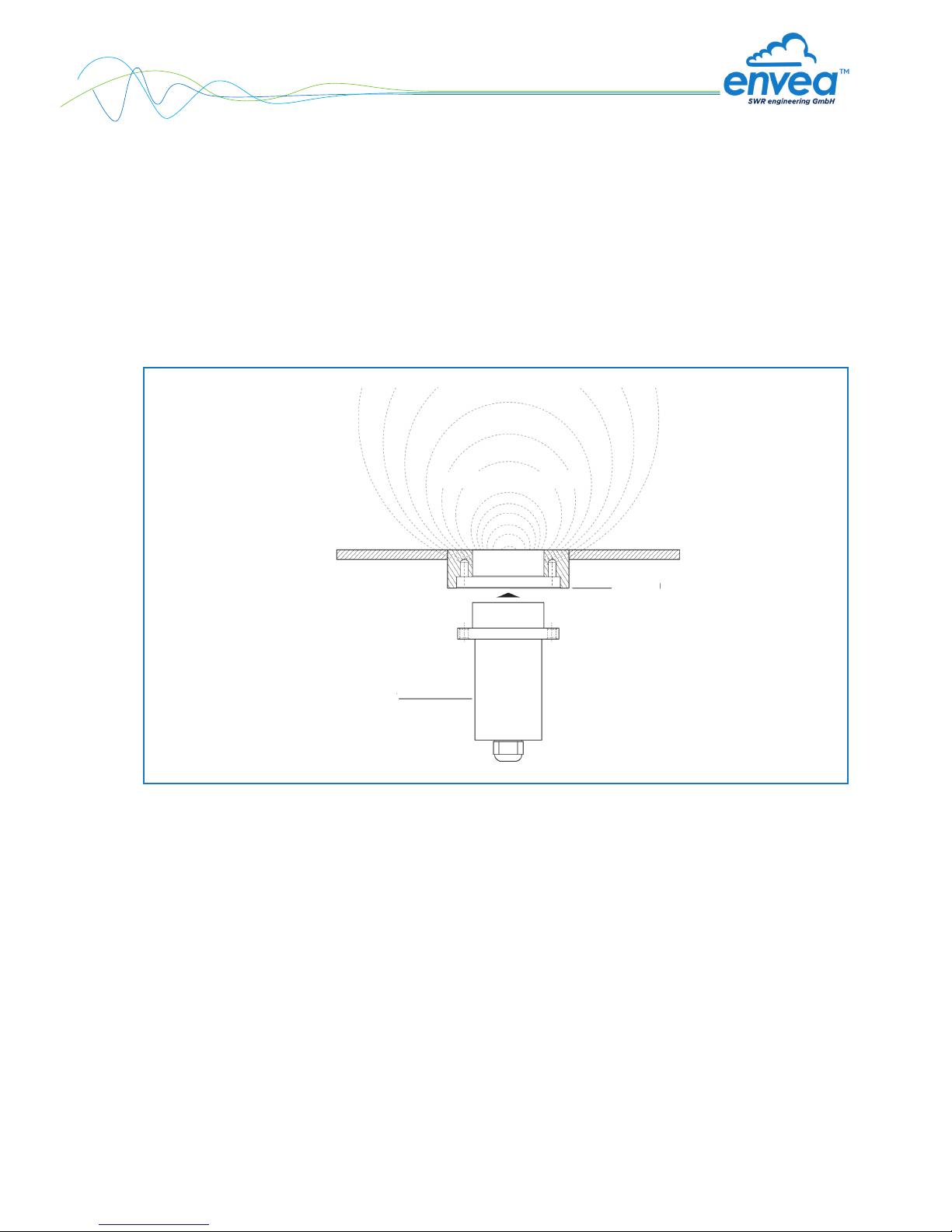
The M-Sens 2 sensor functionality is based on precise high-frequency measurement and direct digitalization
of measured values, where from results a high resolution. As the material surface and capillary moisture
influences strongly its specific conductive capacity, the moisture can be measured exactly by a constant
averaged bulk density. By way of support, any fluctuations of the measuring value caused by the bulk
density are balanced through an internal filter function. Temperature-related fluctuations of the measuring
value are automatically compensated by the sensor. The calibration of the system can easily be carried out
by the operator. On the installed system, the calibration is a matter of pushing a button and entering the
humidity reference value.
Fig. 2: Coupling and reflection of the high frequency
Material to be measured
Flange
Sensor

5
3. Safety
The measuring system M-Sens 2 designed and built according the latest technology has been tested to be safe
and was shipped in safe condition. Nevertheless persons or objects may be endangered by components of the
system if these are operated in an inexpert manner.
The operating instructions must therefore be read in its entirety, and the safety instructions must be adhered to.
If the device is used in a way that does not adhere to its intended and/or proper use, any liability or warranty on
the part of the manufacturer is void.
3.1 Regular use
•Only original spare parts and accessories of ENVEA - SWR engineering must be used.
3.2 Identification of dangers
•Possible dangers when using the measuring system are marked by the following symbols in the
operating instructions:
Warning!
•This symbol in the operating instructions marks actions, which may represent a danger for life and limb
of persons when carried out in an inexpert manner.
Attention!
•All actions which may endanger objects are marked with this symbol in the operating instructions.
3.3 Operational safety
•The measuring system must be installed by trained and authorised personnel only.
•Switch of the power supply for all maintenance, cleaning or inspection works on the tubes or on
components of the M-Sens 2. Follow the notes of the chapter maintenance.
•Before hot-work the sensor must be removed from the installation place.
•The components and electrical connections must be checked for damages regularly.
If a damage is found, it is to repaired before further operation of the instruments.
3.4 Technical progress
•ENVEA - SWR engineering reserves the right to adapt technical data to the technical progress without
particular advance notice. If you have any questions, ENVEA - SWR engineering will be pleased to
inform you on possible changes and extensions of the operating instructions.
6
4. Mounting and installation
4.1 Delivery range
•Transmitter in DIN rail housing
•Sensor
•Operating instructions
•C1-box
•Welding flange
4.2 Auxiliary
•Screw driver 2.5 mm
•Allen key 5 mm
4.3 Mounting of the sensor
M-Sens 2 is designed for continuous moisture measurement. Most important conditions for correct
measurement is the right choice of the mounting place of the sensor. That is, when using chutes or conveyor
belts, it is very important to have a almost even material height in front of the sensor window.
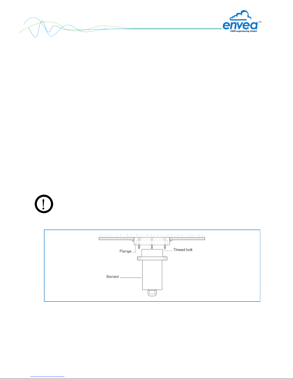
•The flange is welded without sensor and dummy plate in the opening at determined mounting place.
Sensor and dummy plate are mounting by means of plumbing lubricant. For applications without over-
pressure it is possible to renounce the 2 sealing rings.
Attention!
The flange mustn’t be welded together with the sensor or dummy plate (incl. the sealing rings).
7
APPLICATIONS - PRACTICAL EXAMPLES
•Installation in a screw
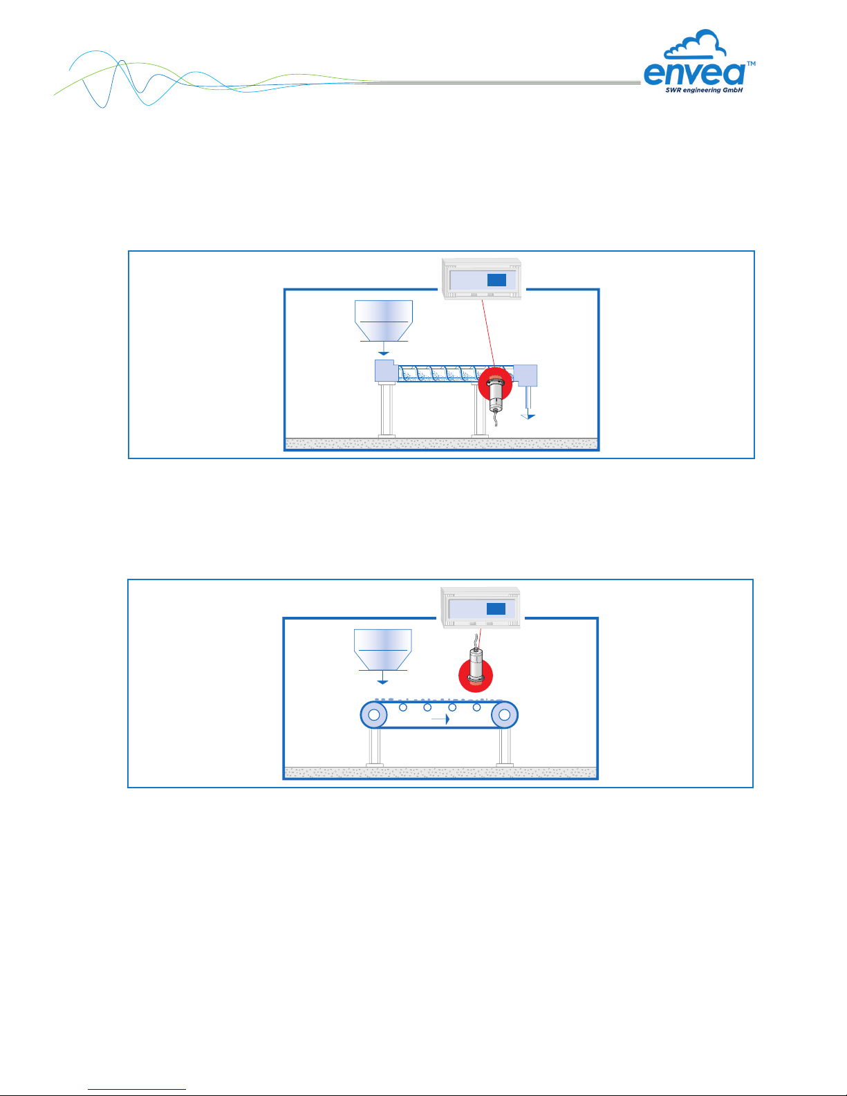
The installation of a moisture sensor in screw feeders proved to be very advantageous, since the
material passes by the sensor window in even intervals and with relatively constant bulk density.
•Installation on a conveyor belt
By means of the online moisture measurement of solids on a conveyor belt, the operator can react in
due time if the material is too humid or too dry. In consequence, plugging of subsequent aggregates
can be prevented.
Screw feeder
13,1
%
Moisture
1,8
%Moisture
Conveyor belt

8
•Installation in a bin
Another installation alternative is to mount a sensor at a bins outlet. Due to constant bulk density in
case of a filled bin, the sensor finds an almost unchanging measuring field for monitoring the residual
moisture. Thus, M-Sens 2 avoids that too damp material reaches the next production level or arrives into
the loading.
•Control of dryer by means of moisture measurement
After the material, lying on the belt, has passed through the dryer tunnel, it gets withdrawn from the
hot air zone. At the end of the belt the dried material falls in a screw conveyor which transports it to the
processing.
The operator queries the following points: Has the material reached really the desired residual moisture
value? That is, has he chosen the right cycle time and temperature?
M-Sens 2 provides accurate and reliable online moisture values for the process control, by which
constant moisture in close tolerances of the output material can be met.
This process optimization enables the operator to manage high savings and quality improvements.
5,2
%Moisture
Bin

9
•Moisture measurement in a mixer
M-Sens 2 can be installed, even later on, in all types of mixers. The measuring values logging is done by
within the moving material during the mixer procedure.
With the measured moisture value of the material in the dryer process parameters like detention time
and dosage quantity can be controlled.
For this purpose M-Sens 2 is connected to a PLC or another process control system.
Mixer

10
4.4 Mounting of the transmitter
The whole electronic equipment can be installed at a maximum distance of 300 m from the sensor.
For assembly in the switching cabinet, the housing is prepared on a top-hat rail in accordance with
DIN EN60715 TH35a.
Fig. 9: DIN-Rail housing for the transmitter
1234
1234
Sensor Transmitter
98
86
36
64
Fig. 10: Field housing for the C1-box
The C1-box contains fuses and resistances in order to guarantee the communication by the ModBus between
sensor and transmitter.
118
35
23
90
1234
567 8
910 11 12
13 14 15 16
USB
PWR
RUN
Andere Handbücher für Envea M-Sens 2
1
Inhaltsverzeichnis
Andere SWR Zubehör Handbücher


