Zubler V6000 Bedienungsanleitung
www.zubler.de
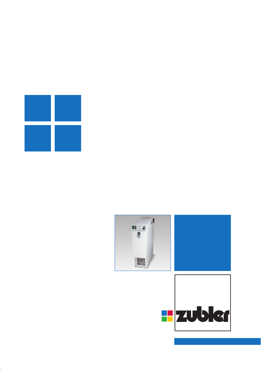
V6000
Individual Vacuuming Unit
O erating instruction 11-2012
en

23
Page
Content
0. Introduction Page 4
0.1 Declaration of conformity
0.2 General hints
0.3 Regular usage
0.4 Environment
0.5 Setting up
0.5.1 Conn. the unit
0.5.2 Conn. the working tool
0.5.3 Remote switching
1. Functions Page 8
1.1 ront panel
1.2 Starting the unit
1.3 Operation
2. Adjustments Page 10
2.1 Sensitivity settings
2.2 Sensitivity adjustment
2.3 KaVo K-Control
3. Filterchange Page 12
3.1 Replacing the filter bag
3.2 Replacing the finefilter
4. Intake system Page 15
4.1 Requirements
4.2 R1200 / R1250
5. Maintenance Page 18
5.1 Replacing the Carbon Brushes
6. Troubleshooting Page 16
7. Data Page 19
7.1 Spare parts
7.2 Dimensions
7.3 Technical data
Page
3
0. Introduction
0.1 Declaration of conformity
Page Page
We, Zubler GmbH
Buchbrunnenweg 26
89081 Ulm-Jungingen /Germany
declare, that the product vacuuming unit
V6000
corresponds to the regulations of the
following directives in regard to
protective requirements
2004/108/EG EMV-Directive
2006/95/EG Low-Voltage Directive
2006/42/EG Machines Directive
Any modification not specifically
approved by us voids the validity of this
declaration.
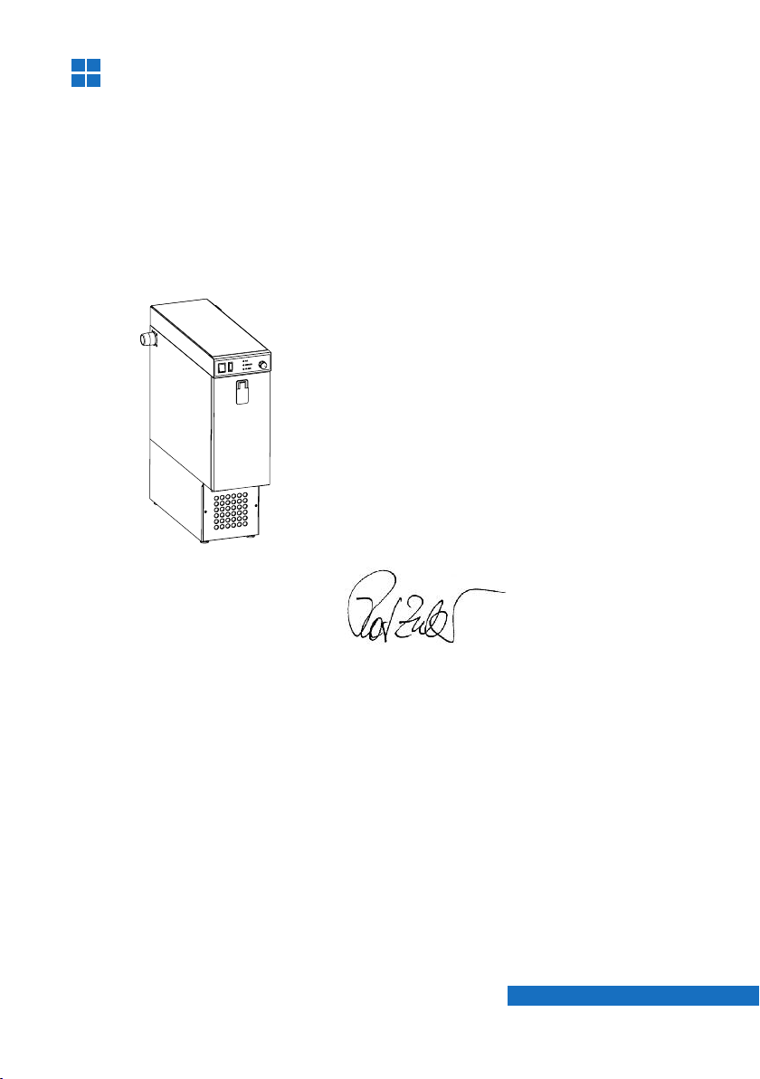
Kurt Zubler
Managing Director

4
0.2 General hints
Dear customer,
we are pleased that you have made the decision to purchase a zubler pro-
duct and wish you a comfortable working with our equipment.
We are asking you to read the instructions carefully before putting the
installation into operation.
The vacuuming unit is especially designed to improve the dust
collection, thus protecting the operator from hazardous dusts. The auto-
matic suction volume adjustment and the two stage filter system, which
corresponds with the DIN EN 60335-2-69 standard (class M), provides an
ideal dust collection and enables an intact room air codition.
0.4 Environment
Temperature +5°C to +40°C
Air humidity max. 80% (@ 30°C)
Max. load max. 1150 W
The vacuuming unit is designed to collect dry dusts only
which are produced in dental laboratories and similar professio-
nal fields (e.g. goldsmith, hearing aid acoustician, model maker).
- The is for indoor usage only !
- Before connecting the to the mains power, check if the volta-
ge given on the number plate corresponds with the specifications of
your local mains power supply.
- or a proper usage a stable mains power supply is required with vol-
tage fluctuations below 10% of the rated value.
- Upon the occurrence of visible dust fall or a sensibly insufficient
vacuuming performance the work must be interrupted immediately
and the installation must be switched off. Inform your dealer or our
service team.
- The use is limited to persons instructed in handling and charged
with the usage.
0.3 Regular usage
PagePage
V6000
V6000
V6000
V6000
5
6
7
5
Zubler Gerätebau
numberplate
Tension XXXXXX
Number:
Fone:
2
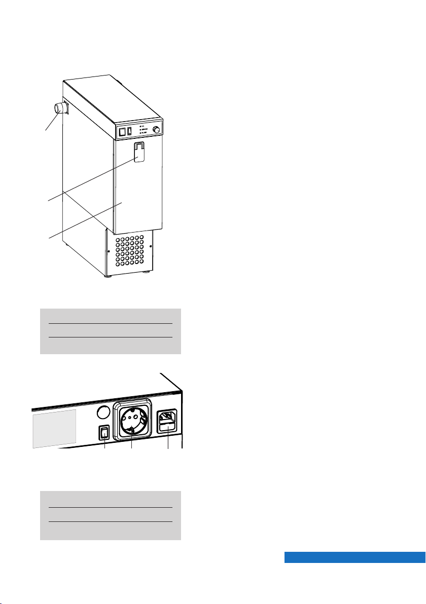
ig. 0.1: front view
■The unit may be used standing upright
only.
■Place the unit on a sufficient stable
and even floor.
■To avoid vibrations take care that the
housing does not touch.
■The exhaust on the front must be
kept free.
1 Door lock
2 Vacuum connector
3 ront door
0.5 Setting up
Page Page
0.5.1 Connecting the unit
■Before connecting the to the
mains power, check if the voltage
given on the number plate corre-
sponds with the specifications of your
local mains power supply.
■Plug the enclosed power cord into the
low-heat-device socket (6) and con-
nect it to a local power socket.
■Connect the enclosed 40mm vacuum
hose to the vacuum connector (2) and
the other side to your intake system.
6 Sensitivity switch
7 Low-heat-device socket
8 Autom. power socket
ig. 0.2: side view
V6000
1
3
6
Mad in
G ramay
C
ZUBLER Gerätebau GmbH
Buchbrunn nw g 26
D-89081 Ulm
T l. +49(0)731 1452-0 / www.zubl r.d
Absauganlag
V6000
Spannung 230V
G samtl istung max. 1150W
Absaugung max. 700W
Automatikst ckdos 450W
V4010 00-11111-22
FP-R24
Netz
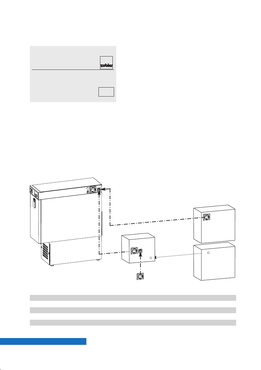
❶
❷
24V
Maschine
ig. 0.3: Remote switching
PagePage
0.5.2 Connecting the technical gear
■Plug in the power cord of the working
tool (e.g. handpiece) into the autom.
power socket(7).
■The power consumption of the wor-
king tool may not exceed 450W !
■In order to make use of the automatic
operation mode the sensitivity must
be set. Choose the best matching
sensitivity setting with the sensitivity
swich (5).
■If the does not start/stop reliab-
le with one of the predefined 3 switch
positions, an internal sensitivity adjust-
ment is required (see chapter 2).
0.5.3 Remote switching (CAD/CAM)
❶If the remote machine offers a swit-
ched power socket, plug the
into the remote power socket.
❷If the remote machine offers a 24V
signal the optional P-R24 and a corre-
sponding connection cable is needed.
(see list below)
Order No.
FP-R24 825/257R24
Connection cable 24V length 2m:
SL-24 - DIN Round plug 4-pin vhf, wieland, shera 825/25600
SL-24 - DE9 D-sub-9 9-pin imes-icore, ammanngirrbach 825/25601
SL-24 - RS stereo phone jack 3,5mm roland 825/25602
SL-24 without plug other 825/25646
V6000
V6000
7
1.
O. K.
Service
Filter
Manual
Auto
14 11 1312
9 10
®
Functions
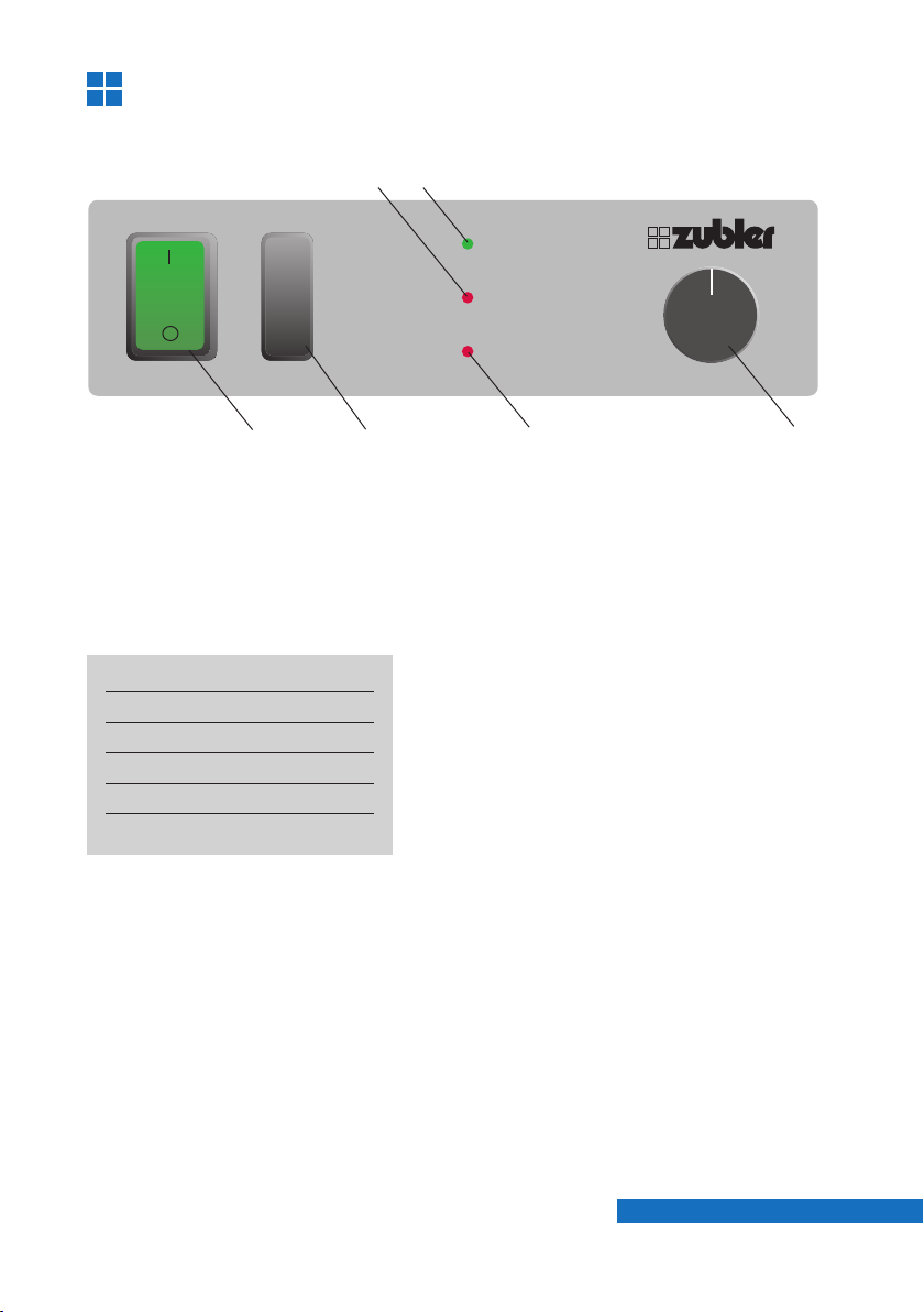
1.1 Front panel
ig. 1.1: ront panel
9 LED Service
10 LED OK
11 Autom. / Manual switch
12 LED ilter
13 Suction volume
14 Main switch
1.2 Starting the unit
■Switch the Automatic / Manual switch
(11) to Manual position to use the
manual operation mode. In this mode
the suction starts immediately after
the vacuuming unit is switched on.
■Switch the main switch (14) to ON
position to start the suction unit.
The main switch is illuminated green.
Adjust the required suction volume
with turn knob (13).
■Switch the Automatic / Manual switch
(11) to Automatic position to use the
automatic operation mode.
In this mode the suction starts
automatically after the technical gear
(e.g. handpiece) is started.
■or sensitivity adjustment see
chapter 2.
Page Page

8
1.3 peration
■The green LED “OK” (10) indicates a
normal operation.
■The red LED “Service” (9) indicates
an electric malfunctioning (e.g. worn
out carbon brushes of the motor).
■The red LED “ ilter” (12) indicates a
filled up filterbag, a clogged finefilter
cartridge or a clogged intake line.
The suction is stopped automatically
and the connected technical gear
cannot be operated.
■Switch O the suction unit with the
main switch (14). Also switch O your
technical gear to avoid an erroneous
startup after the malfunction will have
been remedied. Change the filterbag
and / or the fine filter cartridge and
check the intake line.
■or filterchange see chapter 3.
PagePage
99
B
A
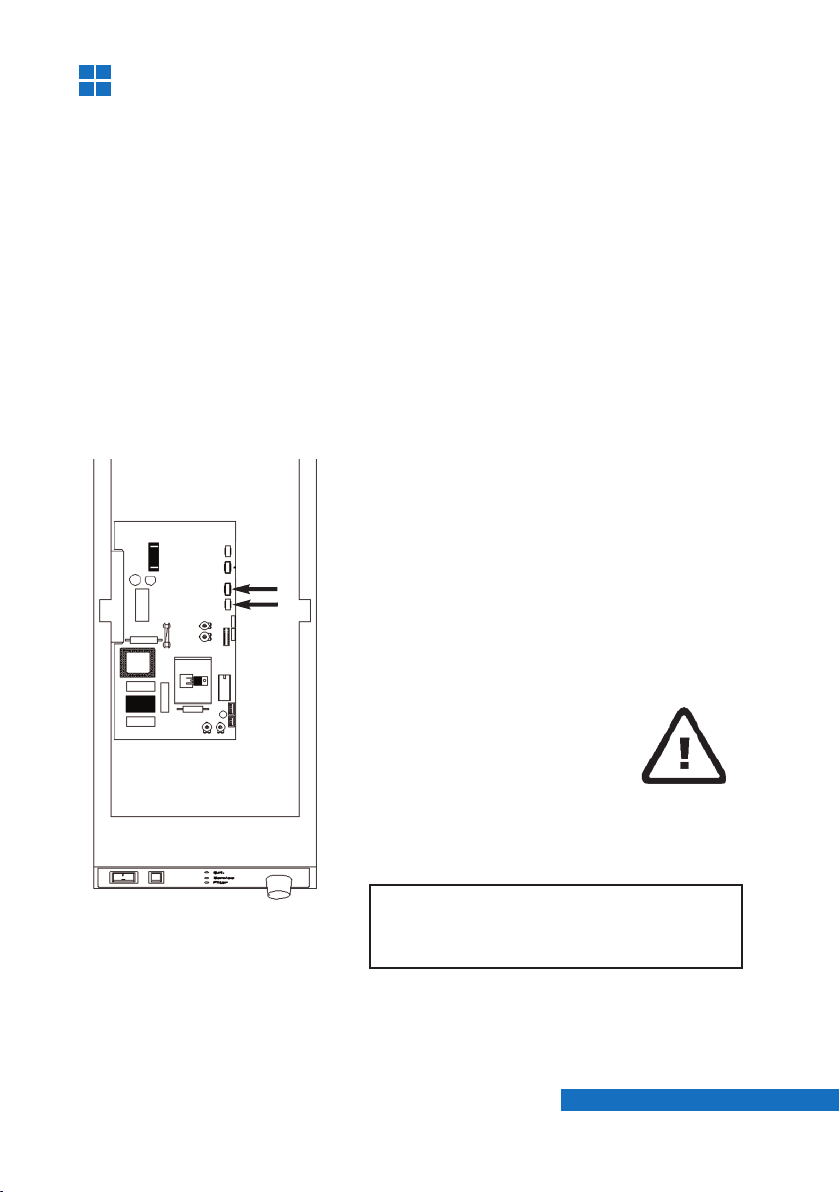
2. Adjustments
ig. 2.1
2.1 Sensitivity settings
Plug in the power cord of the technical gear (e.g. handpiece) into the
automatic socket (27) ( ig.0.2) of the suction unit. The max. load may not
exceed 450W !
Use one of the three predefined sensitivity settings of the external
sensitivity switch (25). The order of the switch positions is as follows :
I: Low sensitivity (Schick CN, KaVo S )
0: Medium sensitivity (W+H Elco 2)
II: High sensitivity (Schick C2 & SM78, KaVo K9, K10)
If your working tool does not work reliable with one of the three sensitivity
switch positions, an internal sensitivity adjustment is necessary.
■Remove the screw which is holding
the top cover.
■Pull the cover carefully backwards and
take it off.
■Remove the ground wire and put the
cover aside.
2.2 Sensitivity adjustment
Attention!
Pull mains plug before opening the
unit!
Page Page
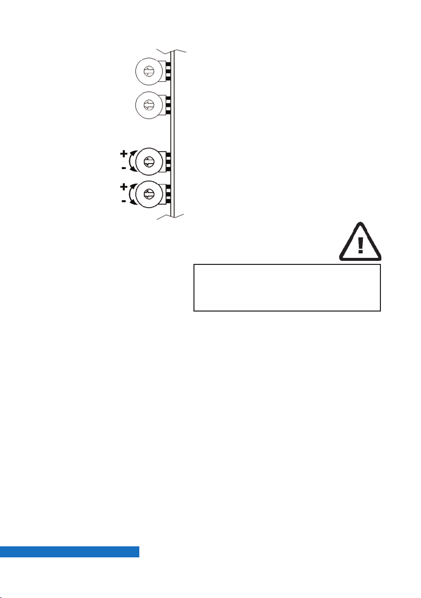
10
■If the external sensitivity switch (5)
( ig. 0.2) is on level II the suction unit
will run continuously, even if the
handpiece is not actuated.
(Sensitivity too high)
■On level 0 the unit will not start with
the lowest rotation speed 5000 rpm.
(Sensitivity too low)
■Switch externally to level 0 and
increase the sensitivity by turning
rheostat B to plus (+) until the unit
starts running.
■Alternatively you may also switch
externally to level II and decrease the
sensitivity by turning the rheostat to
minus (-) until the unit stops running.
2.3 KaVo K-Control
■The adjustment is performed by turning
rheostat B on the PC-board into the
needed direction.
■If the suction unit does not shut O
although the handpiece is not actuated,
the sensitivity is too high. Turn rheostat
B to minus (- = CCW).
■If in a reversed case the suction unit
does not start after actuating the hand-
piece, the sensitivity is too low. Turn
rheostat B to plus (+ = CW).
Take care that neither hoses nor
wires inside the electronic room are
pinched or twisted.
ig. 2.2
B- Sensitivity
A- Damping
PagePage
Inhaltsverzeichnis
Andere Zubler Staubsauger Handbücher


Beliebte Staubsauger Handbücher anderer Marken

Bissell
Bissell LittleGreen Proheat 1425 Series Bedienungsanleitung

Panasonic
Panasonic MC-YL637S147-AE Bedienungsanleitung

NEFF
NEFF N17XH10 0 Series Bedienungsanleitung

LG
LG A9 Series Bedienungsanleitung

Oreck
Oreck Cordless Captura BK51700 Series Bedienungsanleitung

Kogan
Kogan KAVACROBVWA Bedienungsanleitung


