
SLD Security & Communications BTR-3104/250CD Bedienungsanleitung
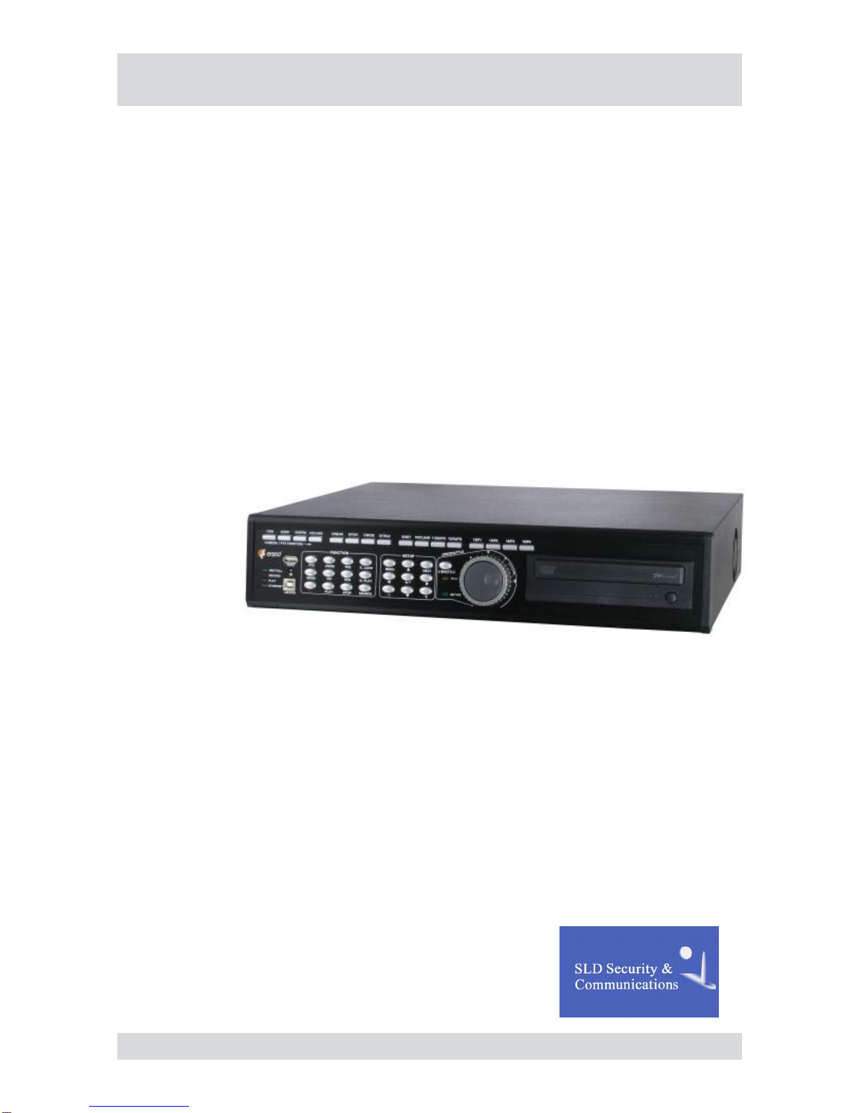
Operating Instructions
Digital Video Recorder
Model: BTR-3104/250CD BTR-3108/250CD
BTR-3104/500CD BTR-3108/500CD
BTR-3104/750CD BTR-3108/750CD
BTR-3116/250CD
BTR-3116/500CD
BTR-3116/750CD


3
BTR-31XX
Safety Instructions
EMC class
This video recorder (DVR) is a classAdevice in accordance with EN 55022.
This device may cause interference to other equipment in domestic use. In such cases the persons opera-
ting the DVR are required to provide appropriate countermeasures, for which they themselves bear the cost.
►
►
Importance of these Operating Instructions
Please read the safety instructions and the other information contained in the Operating Instructions before
connecting up and operating the DVR.
The Operating Instructions should be kept in a safe place for later reference.
►
►
Ambient conditions for the DVR
The DVR should be protected against excessive heat, dust, damp and vibration.
The DVR may only be operated at temperatures between +5°C and +40°C, and up to a maximum air
humidity of 90%.
The DVR may only be operated indoors, and must be protected against incursion of water and damp.
►
►
►
Care of the DVR
Never switch on the DVR when damp has penetrated it. In such cases, have the DVR checked by a qualied
service engineer.
Do not place any heavy objects on the DVR.
Never cover the DVR ventilation slots.
Never insert metallic objects or any other items into the vents. This may permanently damage the DVR.
The housing may only be opened by authorised persons. Repairs may only be carried out by qualied
service personnel.
The DVR must be disconnected from the power supply before its housing is opened.
►
►
►
►
►
►
Getting started with the DVR
When laying the connecting cables, make sure no weight is placed on them, that they are not kinked or
damaged, and that no damp can penetrate them.
►
Cleaning the DVR
The housing of the DVR may only be cleaned with a damp (not wet) cloth,
Use only a mild detergent. Do not use solvent-containing detergents or petrol. This could permanently
damage the surface nish.
►
►
Spare parts
Use only original spare parts from VideorTechnical E. Hartig GmbH.►


5
BTR-31XX
Table of contents
Overview 7
Package contents 7
Basis functions 7
Features 7
Requirements for operation 7
Control options 7
Connections on the rear – BTR-3104 8
Connections on the rear – BTR-3108 9
Connections on the rear – BTR-3116 10
Front panel controls 11
Key to controls 12
Function keys 12
Camera buttons / PTZ functions 13
Menu buttons / PTZ functions 14
Remote control functions 15
Mouse control functions 16
Live mode functions 16
Play mode functions 16
PTZ mode functions 17
Menu overview 18
Accessing the menu 19
Accessing the SYSTEM MENU 19
Accessing the SEARCH MENU 19
Getting started 20
Checklist for starting DVR operation 20
Connecting the remote control and DVR 20
Switching on the DVR 21
Switching off the DVR 21
Administration 22
Dening scheduled entries 22
Deleting recordings 22
Searching for recordings 23
SEARCH BAR 23
TIME/DATE 23
EVENT LIST 24
Menu descriptions – SYSTEM MENU 25
DISPLAY SETUP – SCREEN DISPLAY 26
DISPLAY SETUP – MONITOR SETUP 26
CONFIGURATION – HDD MANAGEMENT 27
CONFIGURATION – TIME/DATE SETUP 28
CONFIGURATION – CAMERASETUP 29
CONFIGURATION – INTERVAL SETUP 31
CONFIGURATION –ALARM SETUP 31

6BTR-31XX
Table of contents
CONFIGURATION – EVENT POPUP SETUP 32
CONFIGURATION – BUZZER SETUP 33
CONFIGURATION – PASSWORD SETUP 33
CONFIGURATION – SYSTEM INFORMATION 33
RECORD SETUP – RECORD CONFIGURATION 34
RECORD SETUP – SCHEDULE SETUP 35
RECORD SETUP – HOLIDAY SETUP 35
BACK-UP – CD-R SETUP 36
BACK-UP – USB SETUP 36
EXTERNAL DEVICE – TCP/IP SETUP 37
EXTERNALDEVICE – RS232C SETUP 40
EXTERNALDEVICE – PANTILT SETUP 41
EXTERNALDEVICE – SPOT MONITOR SETUP 42
EXTERNALDEVICE – REMOCON SETUP 42
FACTORY DEFAULT 43
LANGUAGE 43
Using Integrated Remote Station 44
Menu descriptions – Integrated Remote Station 45
IRS main menu 45
IRS SETUP 46
DVR SETUP 47
VIEWER 48
BACKUP 49
PLAYER 50
TRANSMITTER 51
CLIENT 52
CMS 53
Using DDNS Service 54
Menu descriptions – DDNS Service 56
DDNS Service main menu 56
Specications BTR-3104 57
Specications BTR-3108 59
Specications BTR-3116 61
Index 63
Notes on disposal 66

7
BTR-31XX
Overview
Package contents
Digital video recorder (DVR)
Power supply unit and mains cable
Operating Instructions
Software: Integrated Remote Station (IRS)
Infrared remote control (S Type) including batteries
Mouse
Rubber pad
Hard disk vibration dampers
Screws and mounting brackets
Basis functions
Recording video images using multiple cameras
Event-based recording start
Video playback
Search for specic video sequences
Features
JPEG-2000 compression (H.264)
4, 8 or 16 loop-through inputs / VGA, S-VHS/FBAS outputs
Max. recording speed: 200 eld images per sec (PAL)
Duplex and triplex mode
Memory capacity 250 GB / 500 GB / 750 GB
Maximum video resolution 720 x 288 pixels (PAL)
Various recording criteria possible
Archiving / retrieving images via USB and CD-R
Digital zoom function (2x)
Integral Motion Detector
Telemetry control functions via RS-485 port
Network connection (Ethernet)
Requirements for operation
Digital video recorder BTR connected
At least one camera connected
At least one monitor connected
Control options
Front panel
Remote control
Mouse control
Integrated Remote Station (IRS)
DDNS service
●
●
●
●
●
●
●
●
●
●
●
●
●
●
●
●
●
●
●
●
●
●
●
●
●
●
●
●
●
●
●
●
●
8BTR-31XX
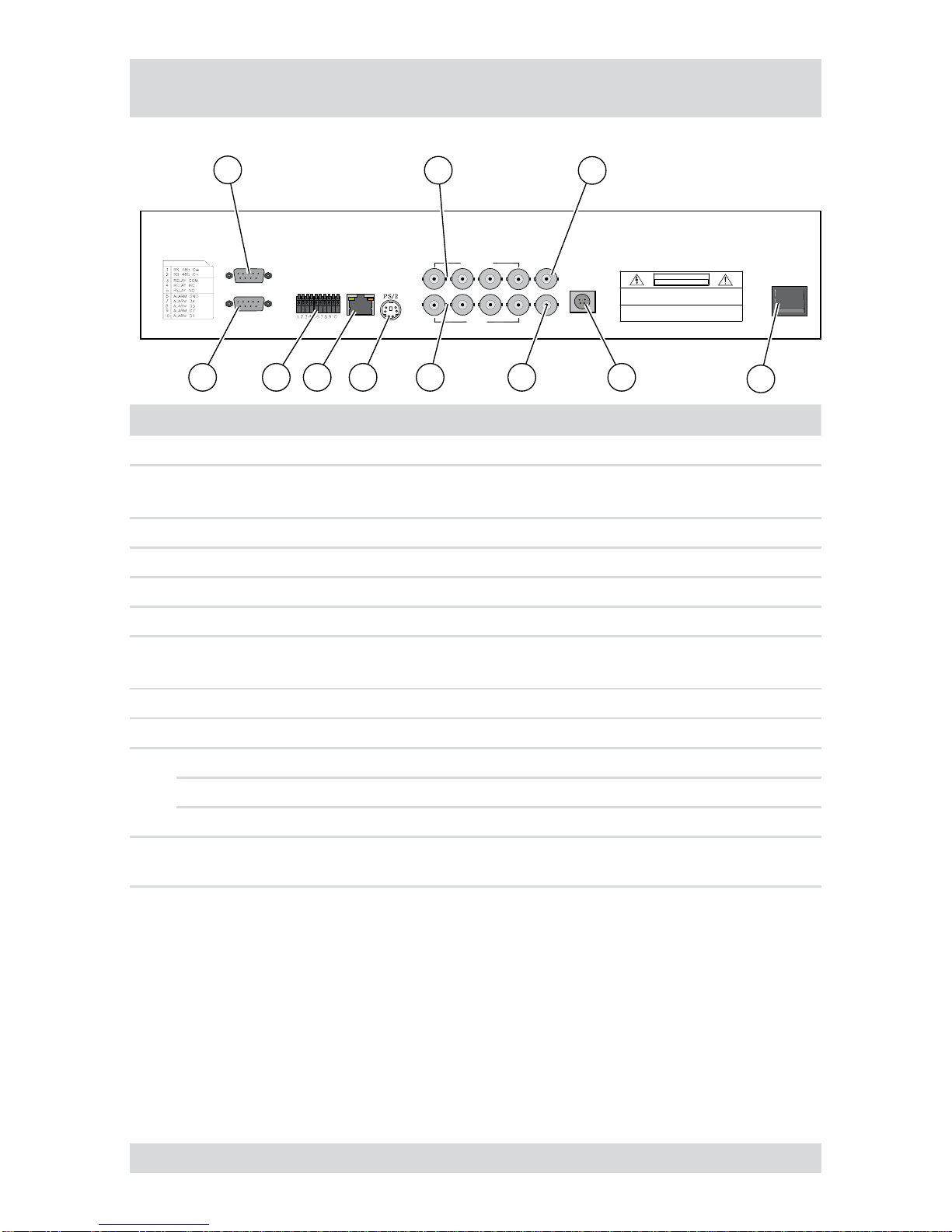
Connections on the rear – BTR-3104
The following diagram and table describe the interfaces at the rear of BTR-3104:
VGA
RS-232 C POWERLOOP
CH3CH2CH1 CH4
SPOT
MONITOR
FUNCTION CAMERAIN
DC12V
ETHERNET
I
O
WARNING : TO PREVENT FIRE OR SHOCK HAZARD DO NOT EXPOSE UNITS. NOT
SPECIFICALLY DESIGNEDFOR OUTDOOR USE TO RAIN OR MOISTURE
CAUTION : TO REDUCE THE RISK OF ELECTRICAL SHOCK DO NOT OPEN COVERS.
NO USER SERVICEABLE PARTS INSIDE. REFER SERVICING TO QUALIFIED
SERVICE PERSONNEL.
CAUTION
RISK OF ELECTRIC
SHOCK. DO NOT OPEN !
123
4
5679 81011
No. Designation Functions/connections Typical devices
1 VGA PC monitor PC monitor
2CAMERAIN
CH1-CH16 Maximum 16 video channels Cameras
3 MONITOR Monitor Monitor
4 POWER ON/OFF switch -
5 Power supply Power Supply -
6 SPOT Spot monitor Monitor
7LOOP
CH1-CH16 Maximum 16 loop-through video channels Cameras
8 PS/2 External interface Mouse
9 ETHERNET Network Network cable
10
RS 485 Connection to the PTZ camera PTZ cameras
RELAY Relay alarm output for external devices Sirene, warning light
ALARM Sensor input Sensors
11 RS-232 C External interface PC (operation via PC key-
board)
9
BTR-31XX
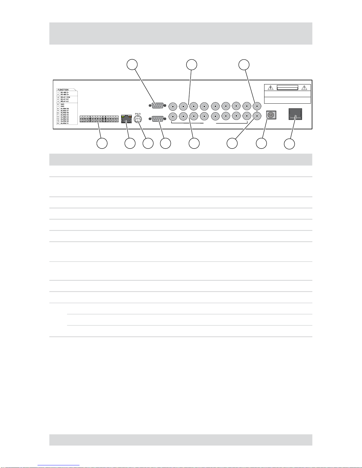
Connections on the rear – BTR-3108
The following diagram and table describe the interfaces at the rear of BTR-3108:
CH3CH2CH1 CH4 CH7CH6CH5 CH8
LOOP
MONITOR
SPOT
15
14
13
12
11
10
9
8
7
6
5
4
3
2
1
VGA
RS-232 C POWER
DC12V
ETHERNET I
O
WARNING : TO PREVENT FIRE OR SHOCK HAZARD DO NOT EXPOSE UNITS. NOT
SPECIFICALLY DESIGNEDFOR OUTDOOR USE TO RAIN OR MOISTURE
CAUTION : TO REDUCE THE RISK OF ELECTRICAL SHOCK DO NOT OPEN COVERS.
NO USER SERVICEABLE PARTS INSIDE. REFER SERVICING TO QUALIFIED
SERVICE PERSONNEL.
CAUTION
RISK OF ELECTRIC
SHOCK. DO NOT OPEN !
123
4
5679 81011
No. Designation Functions/connections Typical devices
1 VGA PC monitor PC monitor
2CAMERAIN
CH1-CH16 Maximum 16 video channels Cameras
3 MONITOR Monitor Monitor
4 POWER ON/OFF switch -
5 Power supply Power Supply -
6 SPOT Spot monitor Monitor
7LOOP
CH1-CH16 Maximum 16 loop-through video channels Cameras
8 RS-232 C External interface PC (operation via PC key-
board)
9 PS/2 External interface Mouse
10 ETHERNET Network Network cable
11
RS 485 Connection to the PTZ camera PTZ cameras
RELAY Relay alarm output for external devices Sirene, warning light
ALARM Sensor input Sensors
10 BTR-31XX
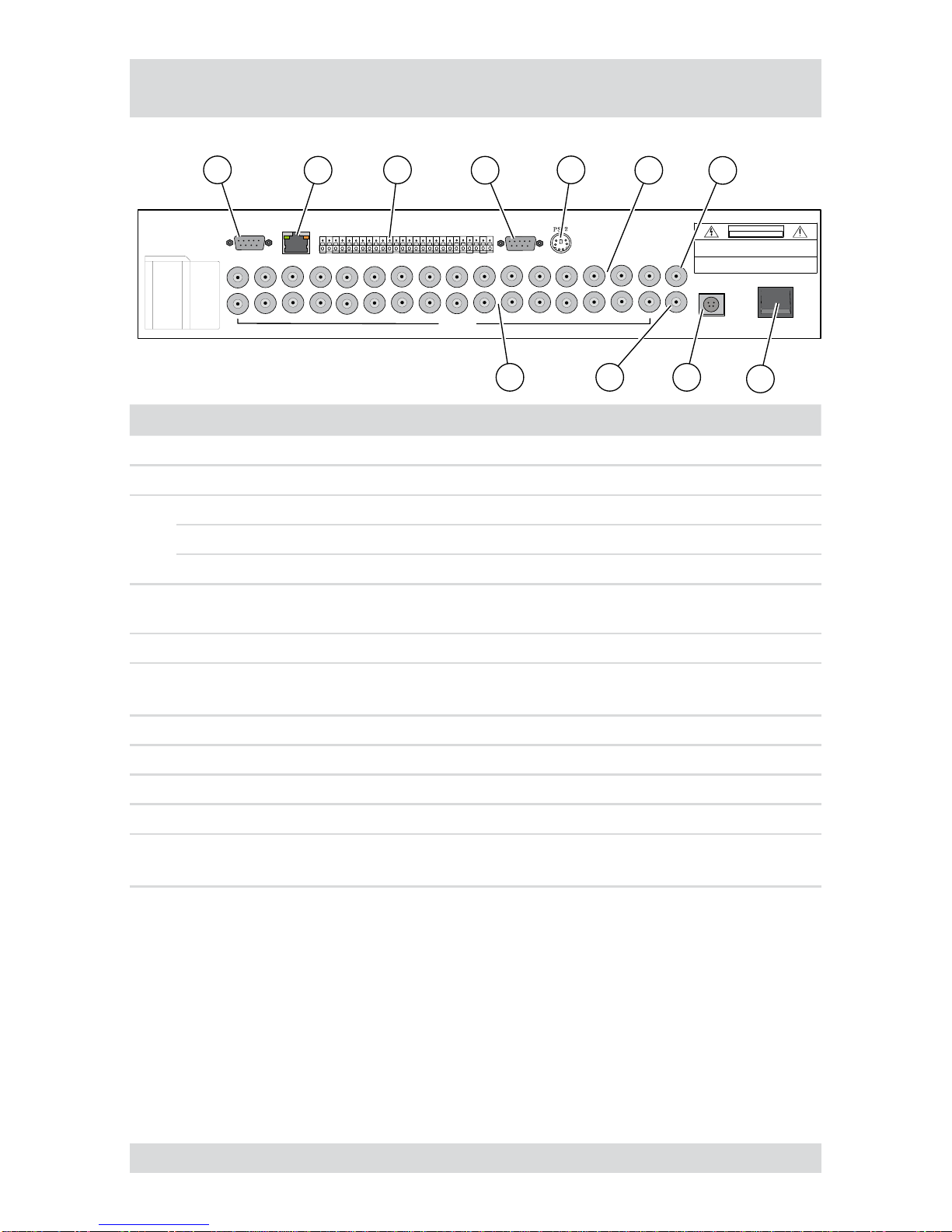
Connections on the rear – BTR-3116
The following diagram and table describe the interfaces at the rear of BTR-3116:
VGA RS-232 C
FUNCTION
CH3CH2
CH1 CH4CH3CH2
CH1 CH4CH3
CH2CH1 CH4 CH3CH2
CH1 CH4
LOOP
MONITOR
SPOT
262524232221201918171615141312111098765
4
321
POWER
DC12V
ETHERNET
I
O
WARNING : TO PREVENT FIRE OR SHOCK HAZARD DO NOT EXPOSE UNITS. NOT
SPECIFICALLY DESIGNEDFOR OUTDOOR USE TO RAIN OR MOISTURE
CAUTION : TO REDUCE THE RISK OF ELECTRICAL SHOCK DO NOT OPEN COVERS.
NO USER SERVICEABLE PARTS INSIDE. REFER SERVICING TO QUALIFIED
SERVICE PERSONNEL.
CAUTION
RISK OF ELECTRIC
SHOCK. DO NOT OPEN !
1234567
8
91011
FUNCTION
RS 485 D-1 RS 485 D+2 GND3 RELAY COM4 RELAY NC5 RELAY NO6 GND
7ALARM D168 ALARM D159 ALARM D1410 ALARM D1311 GND12 ALARM D1213
ALARM D1114 ALARM D1015 ALARM D916 GND17 ALARM D818 ALARM D719 ALARM D620 ALARM D521 GND22 ALARM D423 ALARM D324 ALARM D225 ALARM D126
No. Designation Functions/connections Typical devices
1 VGA PC monitor PC monitor
2 ETHERNET Network Network cable
3
RS 485 Connection to the PTZ camera PTZ cameras
RELAY Relay alarm output for external devices Sirene, warning light
ALARM Sensor input Sensors
4 RS-232 C External interface PC (operation via PC key-
board)
5 PS/2 External interface Mouse
6CAMERAIN
CH1-CH16 Maximum 16 video channels Cameras
7 MONITOR Monitor Monitor
8 POWER ON/OFF switch -
9 Power supply Power Supply -
10 SPOT Spot monitor Monitor
11 LOOP
CH1-CH16 Maximum 16 loop-through video channels Cameras
Dieses Handbuch passt für folgende Modelle
8
Inhaltsverzeichnis
Andere SLD Security & Communications DVR Handbücher


